5-39
BVW-55 P2
Adjustment procedure
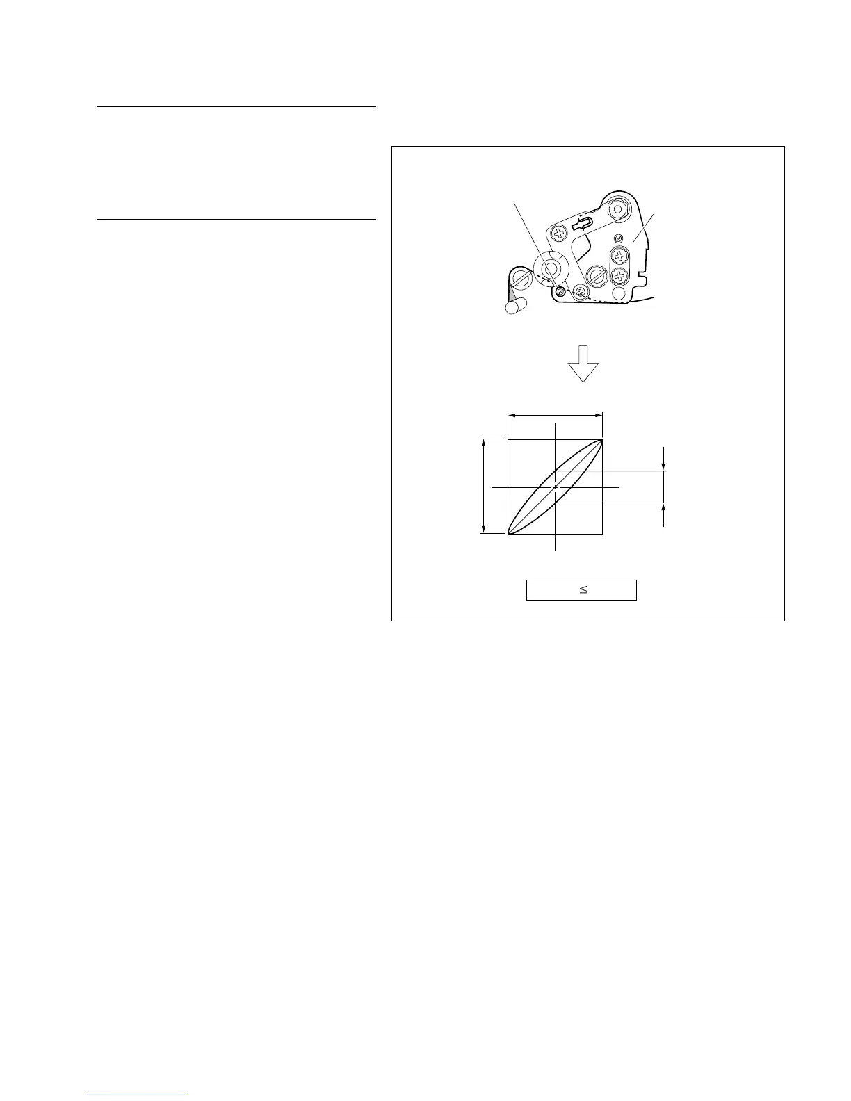
8. Adjust the AT head azimuth
Turn the azimuth adjustment screw so that the
specification is satisfied.
In Case the Adjustment is Performed
9. Adjust the AT head head-to-tape
contact
(Refer to Section 5-11.)
10. Adjust the AT head position
(Refer to Section 5-8. )
11. Check the AT head height
(Refer to Section 5-9.)
12. Check the AT head azimuth
(Refer to steps 6 and 7 in this section.)
13. Re-check the AT head
(Rerform the steps 9 and 10 again.)
14. Locking compound applying
(Refer to Section 5-1.)
n
After adjustment are completed, be sure to set
S100-1 switch on the SV-206 board to OFF
position.
5-10. AT Head Azimuth Check and Adjustment
6 cm
6 cm A
Spec. A 0.52 cm
AT head
Azimuth adjustment screw
. Alignment tape : CR8-1A (3:00 to 4:55)





 To Next Page