3-11
BVW-55
(Ex.: When pressing the switch 7)
INPUT CHECK
C000:CASSETTE SW
1:REEL HUB 2:METAL/OX
3:THICKNESS 4:SPARE
5:SPARE 6:DGTL/ANLG
7:METAL REC INHIBIT
8:OXIDE REC INHIBIT
7 1 3 8
SW 87654321 425
00000000 6
INPUT CHECK
C000:CASSETTE SW
1:REEL HUB 2:METAL/OX
3:THICKNESS 4:SPARE
5:SPARE 6:DGTL/ANLG
7:METAL REC INHIBIT
8:OXIDE REC INHIBIT
7 1 3 8
SW 87654321 425
00000000 6
C000 : CASSETTE SW
This submenu checks the functions of cassette tab sensors and REC inhibit sensors
(switches).
(1) Press each sensor (switch) with fingers.
. Confirm that “0” below the corresponding switch number changes to “1”.
(2) Release the fingers.
. Confirm that “1” below the corresponding switch number returns to “0”.
(3) Press the MENU button when terminating the check.
In case of NG
When cassette tab sensors (1 to 6) are NG
. Check the corresponding sensor (S400 to S405) on the SV-206 board.
. Check the sensor input port of MPU (IC402 on the SV-206 board).
When REC inhibit sensor (METAL tape) 7 is NG
. Check the sensor (S406) on the SV-206 board.
. Check the sensor input port of MPU (IC402 on the SV-206 board).
When REC inhibit sensor (OXIDE tape) 8 is NG
. Check the sensor (PH400) on the SV-206 board.
. Check the sensor input port of MPU (IC402 on the SV-206 board).
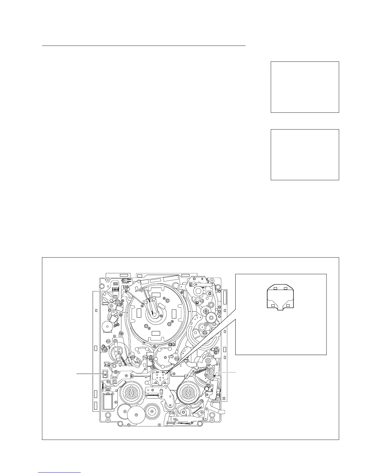
Locations of Sensors (Switches)
3-2. TAPE Maintenance Mode (M0)
3-2-2. SERVO CHECK Mode (C0)
1
42
6
3
5
7
REC
inhibit
sensor
(METAL tape)
8
REC inhibit sensor
(OXIDE tape)
1 Reel hub sensor
2 Metal/oxide tape sensor
3 Tape thickness sensor
4 Spare sensor 2
5 Spare sensor 1
6 Degital/analog tape sensor
Cassette tab sensors