1-16
DSR-2000/2000P
1-1. DSR-2000
Location and Function of Parts
Chapter 1 Overview
30
Chapter 1 Overview
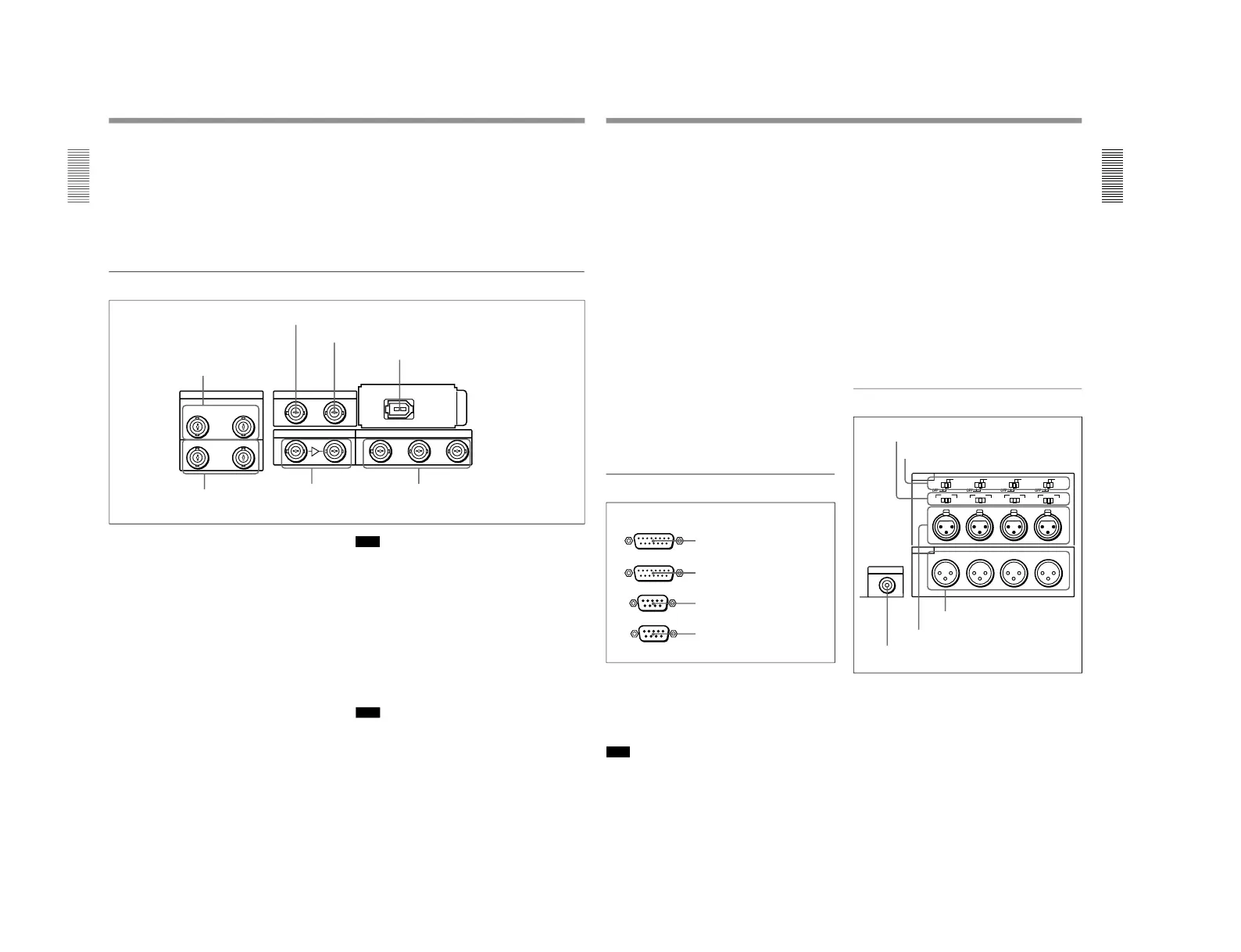
8 COMPONENT VIDEO Y/R
–Y/B–Y IN
connectors (BNC type)
Input analog component video signals (Y/R−Y/B−Y)
to these connectors.
9 COMPONENT VIDEO Y/R
–Y/B–Y OUT
connectors (BNC type)
These connectors output analog component video
signals (Y/R−Y/B−Y).
!º VIDEO OUT 1, 2, and 3 (SUPER) connectors
(BNC type)
These connectors output analog composite video
signals.
When the CHARACTER switch on the subsidiary
control panel is set to ON, connector 3 (SUPER)
outputs a signal with superimposed text information.
2 Digital input/output section
DIGITAL AUDIO I/O(AES/EBU) SDTI(QSDI)
SDI INPUT SDI OUTPUT
i.LINK
OUT
(SUPER)
IN
INPUT OUTPUT
123
CH-1/2
CH-1/2
CH-3/4
CH-3/4
1 DIGITAL AUDIO (AES/EBU) IN connectors
2 SDTI(QSDI) INPUT connector
3 SDTI(QSDI) OUTPUT connector
4 i.LINK connector (optional DSBK-190
i.LINK/DV Input/Output Board)
5 DIGITAL AUDIO
(AES/EBU) OUT connectors
6 SDI INPUT connectors
7 SDI OUTPUT 1, 2, and 3 (SUPER)
connectors
1 DIGITAL AUDIO (AES/EBU) IN connectors
(BNC type)
Input digital audio signals in AES/EBU format to these
connectors.
The left-hand connector (CH-1/2) is for audio channels
1 and 2, and the right-hand connector (CH-3/4) is for
audio channels 3 and 4.
2 SDTI (QSDI) (Serial Data Transport Interface
(QSDI)) INPUT connector (BNC type)
Input digital video and audio signals in SDTI (QSDI)
format to this connector.
3 SDTI (QSDI) (Serial Data Transport Interface
(QSDI)) OUTPUT connector (BNC type)
This connector outputs digital video and audio signals
in SDTI (QSDI) format.
Note
If you monitor the output signal from this connector on
another device in E-E mode while making a search at
speeds in the range +1 to +
1
/
30
or –
1
/
30
to –1 times
normal speed, the signal may sound differently than it
does on this unit.
4 i.LINK connector (6-pin IEEE-1394)(optional
DSBK-190 i.LINK/DV Input/Output Board)
This connector is available when the optional DSBK-
190 i.LINK/DV Input/Output Board is fitted.
This connector inputs and outputs digital video and
audio signals in DV format.
Note
If you monitor the output signal from this connector on
another device in E-E mode while making a search at
speeds in the range +1 to +
1
/
30
or –
1
/
30
to –1 times
normal speed, the signal may sound differently than it
does on this unit.
Chapter 1 Overview
Chapter 1 Overview
31
5 DIGITAL AUDIO (AES/EBU) OUT connectors
(BNC type)
These connectors output digital audio signals in AES/
EBU format.
The left-hand connector (CH-1/2) is for audio channels
1 and 2, and the right-hand connector (CH-3/4) is for
audio channels 3 and 4.
Digital audio signals are always output from this unit
at a sampling frequency of 48 kHz.
6 SDI (Serial Digital Interface) INPUT connectors
(BNC type)
Input digital video and audio signals in SDI (D1)
format to the left-hand connector. The right-hand
connector is for an active-through connection.
7 SDI (Serial Digital Interface) OUTPUT 1, 2 and
3 (SUPER) connectors (BNC type)
These connectors output digital video and audio
signals in SDI (D1) format.
When the CHARACTER switch on the subsidiary
control panel is set to ON, connector 3 (SUPER)
outputs a signal with superimposed text information.
Digital audio signals are always output from this unit
at a sampling frequency of 48 kHz.
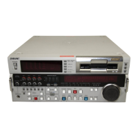
3 External device connectors
1 VIDEO CONTROL connector (D-sub 15-pin)
For remote control of the internal digital video
processor, connect an optional remote control unit
such as the UVR-60/60P or BVR-50/50P to this
connector.
Note
Always power off this unit before connecting the
remote control unit.
1 VIDEO CONTROL connector
REMOTE-OUT
REMOTE-IN
VIDEO CONTROL
CONTROL PANEL
2 CONTROL PANEL connector
3 REMOTE-IN connector
4 REMOTE-OUT connector
2 CONTROL PANEL connector (D-sub 15-pin)
When using the optional DSBK-200 Control Panel to
remotely control this unit, connect the DSBK-200 to
this connector.
3 REMOTE-IN connector (D-sub 9-pin)
When controlling this unit from an editing controller
such as the ES-7, PVE-500, BVE-600/800/910, or
RM-450/450CE, connect the unit to the editing
controller via this connector using the supplied 9-pin
remote control cable.
When controlling another VCR from this unit, connect
the VCR to this connector.
4 REMOTE-OUT connector (D-sub 9-pin)
This connector provides the loop-through output for
remote control signals from the REMOTE-IN
connector.
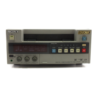
4 Analog audio input/output section
1 AUDIO IN −6dBm/0dBm/+4dBm switches
Set these switches according to the audio input levels
to the AUDIO IN CH-1 to CH-4 connectors.
MONITOR AUDIO
AUDIO IN
LEVEL
AUDIO OUT
CH-1
CH-2
CH-3
CH-4
CH-1
0dBm
HIGHLOW
OFF
-6dBm +4dBm
CH-2 CH-3
CH-4
0dBm
-6dBm +4dBm
0dBm
-6dBm +4dBm
0dBm
-6dBm +4dBm
ON
-600
Ω
LEVEL
HIGHLOW
OFF
ON
-600
Ω
LEVEL
HIGHLOW
OFF
ON
-600
Ω
LEVEL
HIGHLOW
OFF
ON
-600
Ω
1 AUDIO IN −6dBm/0dBm/+4dBm switches
2 AUDIO IN LEVEL/600Ω switches
3 MONITOR AUDIO connector
4 AUDIO IN CH-1 to CH-4 connectors
5 AUDIO OUT CH-1 to CH-4
connectors