1-75
DSR-2000/2000P
1-1. DSR-2000
Appendixes
148
Appendixes
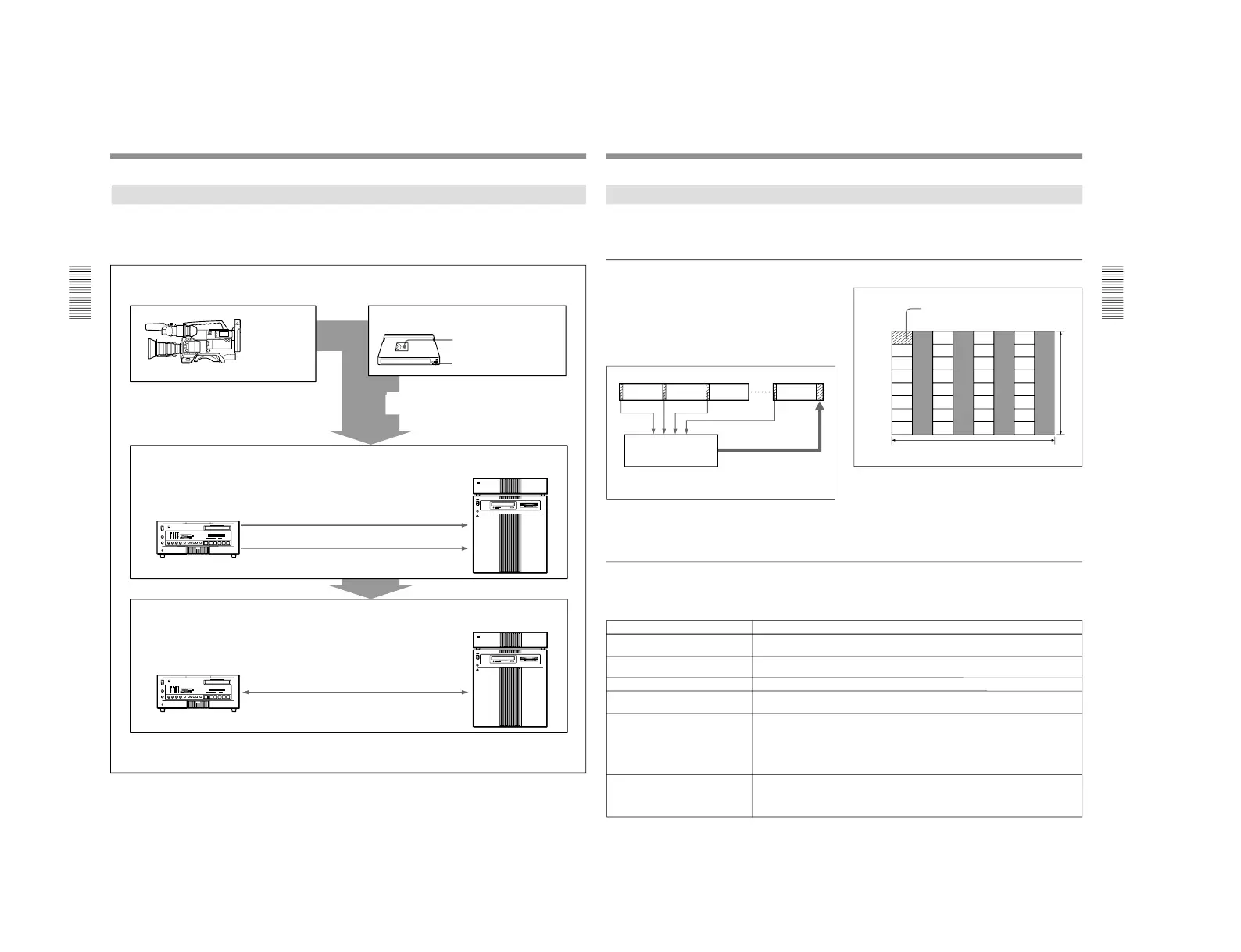
Example System Configuration and Operation Flow
The following illustration shows an example system
configuration for using the ClipLink function and a
typical ClipLink operation flow.
Shooting
DVCAM
camcorder (DSR-
130/130P/300/
300P/500WS/
500WSP)
DVCAM standard cassette or DVCAM mini cassette
Index Pictures: recorded on
tape
ClipLink log data: recorded in
cassette memory
ClipLink log data tranfer
ES-7 EditStation
™
non-linear editing
system
DSR-2000/85/1800/1600
a)
(or DSR-2000P/85P/1800P/
1600P
a)
) Digital
Videocassette Recorder
Video output (QSDI)
Index Pictures
ClipLink log data
RS-422A interface
Editing
Actual AV data
QSDI input/output
ES-7 EditStation
™
non-linear editing
system
DSR-2000/85
b)
/1800/1600
a)
(or DSR-2000P/85P
b)
/1800P/
1600P
a)
) Digital
Videocassette Recorder
a) The DSR-1600/1600P is a videocassette player.
b) Between the DSR-85/85P and ES-7, quadruple transfer is possible through the QSDI.
ClipLink log data recorded onto DVCAM
cassettes links shooting and editing operations.
ClipLink
Guide
Appendixes
Appendixes
149
Data Generated When Shooting
The following describes the kinds of data that is
generated when using the ClipLink function.
Index Pictures
When shooting, a single-frame image from the Mark
IN point at the start of each scene is recorded as a still
picture into the DSR-1/1P
’s internal memory. These
images are called
“Index Pictures”. When you finish
shooting, the Index Pictures from all scenes are
recorded onto the tape after the last scene.
Up to 32 Index Pictures can be recorded onto the tape
space normally occupied by one frame, as shown
below.
Seven frame spaces are reserved at the end of the last
scene as a recording area for Index Pictures. (A
cassette with 16 Kbits of cassette memory can record
up to 198 Index Pictures, and a cassette with 4 Kbits of
cassette memory can record up to 45 Index Pictures.)
Tape
After shooting, the Index
Pictures in the internal
memory are recorded onto the
video tape.
DVCAM camcorder
’s
internal memory
Scene 1 Scene 2
Scene 3
Scene n
1
5
9
13
17
21
25
29
2
6
10
14
18
22
26
30
3
7
11
15
19
23
27
31
4
8
12
16
20
24
28
32
0 90 180 270 360 450 540 630
60
120
180
240
300
360
420
NTSC
(72)
(144)
(216)
(288)
(360)
(432)
(504)
(PAL)
Index Picture
720 dots
480 lines (NTSC) or 576 lines (PAL)
ClipLink log data
ClipLink log data can be recorded automatically or
manually into the cassette memory for use as a
convenient alternative to the conventional
“shot list”.
ClipLink log data includes the following items.
This cannot be changed (set to
“1” at shipping).
ClipLink log data
Reel number (cassette number)
Description
Data (maximum length: 8 digits) consisting of alphanumeric characters and/or
symbols (This is left blank at shipping.)
OK/NG Indicates the OK/NG status of a particular scene. (In the OK case, nothing is
recorded.)
Mark IN/OUT point time codes These are the time codes that indicate the Mark IN and Mark OUT points for each
scene (HH:MM:SS). These time codes are recorded when the camera has been set to
MARK mode.
The frame digit is incremented at each Mark IN point and is decremented at each Mark
OUT point. (For details, see
“Time codes recorded for Mark IN/OUT points
” on page
151.)
This is the time code that indicates the cue points (valid up to the frame digit). This
time code is recorded when the camera has been set to CUE mode. When in this
mode, the time codes at the start and end of a recording (the Rec IN and Rec OUT
time codes) are automatically recorded as Mark IN/OUT points.
Take number
Scene number A three-digit number from 001 to 198 (starts at 001 and is automatically incremented
with each scene).
Cue point time code