2-17
HDS-7150/7100
HDS-7150/7100
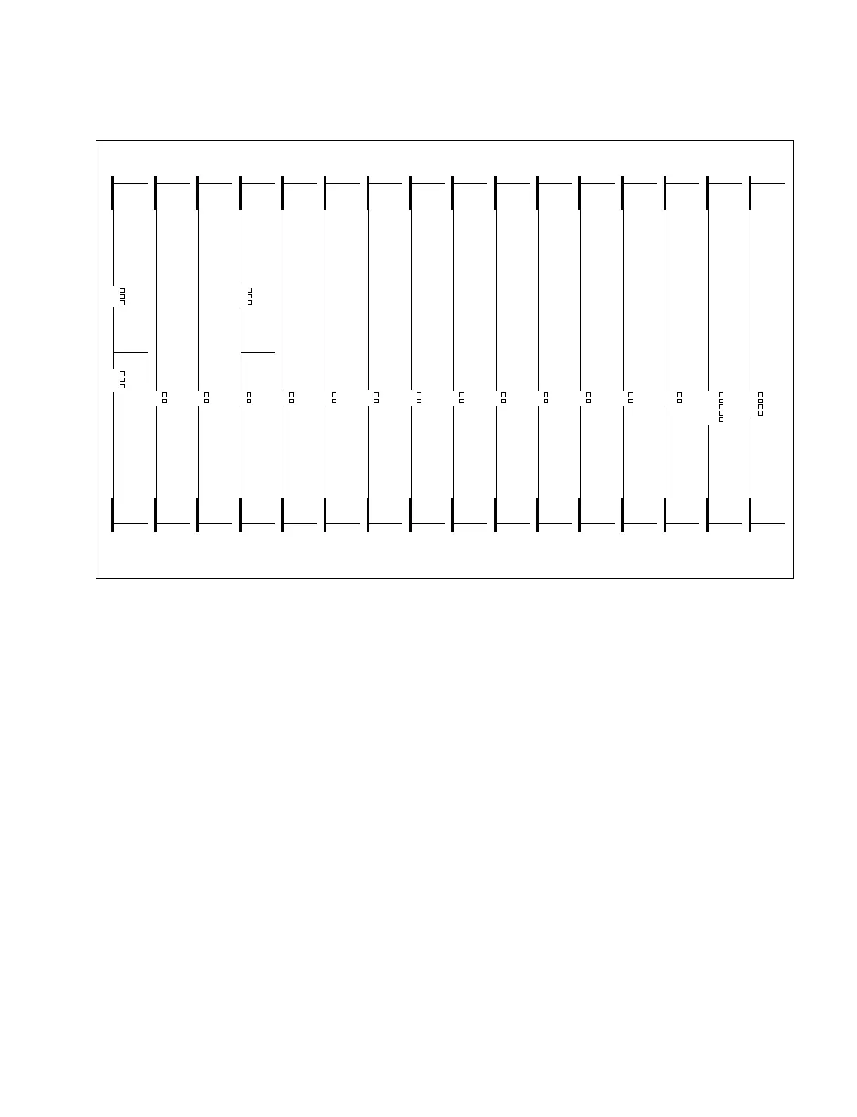
2-7. Description of Switches and LEDs on Boards
. Location of power indicator on the boards
The +5 V, +3 V, _5 V and _12 V are supplied from the power supply unit HKDS-7695/7695A to the HDS-7150/7100 and
optional boards.
The power indicators light when the power is supplied.
The power indicators go out when the power is not supplied or fuses on the boards are blown.
The _2 V on the DI-37 and OUT-20 boards are generated by the DC to DC coverter on the respective boards.
CPU-183
VSE-19 DLP-17
MEM-65Y MEM-65C MEM-65K
VSE-20 MIX-43VSE-21 CRK-9
WKG-29
VSW-66 DSK-16 DI-37 OUT-20
CKG-26
D5
D6
D7
D1
D2
D3
D4
D3
D4
D3
D4
D2
D4
D2
D3
D1
D2
D39
D40
D1
D2
D13 (+ 5 V)
D14 (+ 3 V)
D15 (_ 5 V)
+12 V
+5 V
+3 V
VCC
VDD
VEE
+5 V
+3 V
+5 V
+3 V
+5 V
+3 V
+5 V
+3 V
+5 V
+3 V
D3
D4
+5 V
+3 V
D3
D4
+5 V
+3 V
D3
D4
+5 V
+3 V
D1
D6
+5 V
+3 V
+5 V
+3 V
+5 V
+3 V
+5 V
+3 V
+5 V
+3 V
D1
D2
D3
D4
D35
A
B
+5 V
+3 V
_5 V
_2 V
D7
D8
D9
D10
+5 V
+3 V
_5 V
_2 V
Front view
SLOT
NO. 1
SLOT
NO. 16
CPU-183
MPU-111
D5
D6
D7
+12 V
+5 V
+3 V