3-8
HDS-7150/7100
HKDS-7695/7695A
3-5. Input and Output Signals of Connectors
3-5. Input and Output Signals of Connectors
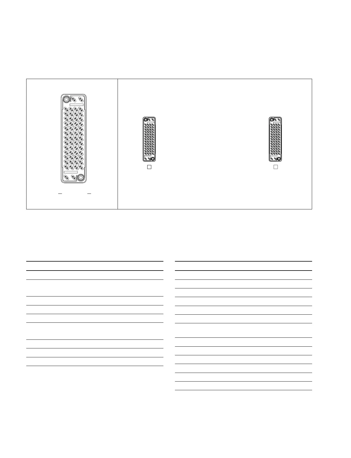
The input and output signals of the connectors on the rear panel are specified in the following table. And
refer to the following illustration for the pin positions of the connectors.
PROCESSOR B : (D-sub 56-pin, Female)
<DEVICE> from HDS-7150/7100
Pin No. Signal Name Function
1 +3 V SENS+ +3 V Sense+
2 +3 V SENS– +3 V Sense_
3 _5 V SENS+ _5 V Sense+
4 _5 V SENS– _5 V Sense_
5-16 +3 V Power supply +3 V
17-21, 23-24 +5 V (B) Power supply +5 V (B)
22, 25-43, GND Frame ground
45-47, 49-51
44, 48 +12 V Power supply +12 V
52 _5 V Power supply _5 V
53 +5 V (B) SENS++5 V (B) Sense+
54 +5 V (B) SENS_+5 V (B) Sense_
55 +12 V SENS++12 V Sense+
56 +12 V SENS_+12 V Sense_
n
The <DEVICE> indicates the controlled device.
PROCESSOR A : (D-sub 56-pin, Female)
<DEVICE> from HDS-7150/7100
Pin No. Signal Name Function
1 +5 V (C) SENS++5 V (C) Sense+
2, 6, 9-11, +5 V (A) Power supply +5 V (A)
13-28, 31, 32
3, 4, 7, 8 +5 V (C) Power supply +5 V (C)
5 +5 V (C) SENS_+5 V (C) Sense_
12 +5 V (A) SENS++5 V (A) Sense+
29, 30, 33-35, GND Frame ground
37-54
36 +5 V (A) SENS_+5 V (A) Sense_
55 AC ERROR AC Error
56 DC ERROR DC Error
Rear panel
[D-sub 56-pin, Female]
EXT VIEW
PROCESSOR
B
PROCESSOR
A
ELCO 8070
>PBT+GF30<
+PS3
+PS3
ELCO 8070
>PBT+GF30<
+PS3
+PS3
ELCO 8070
>PBT+GF30<
+PS3
+PS3
Pin position