6-5
HDS-7150/7100
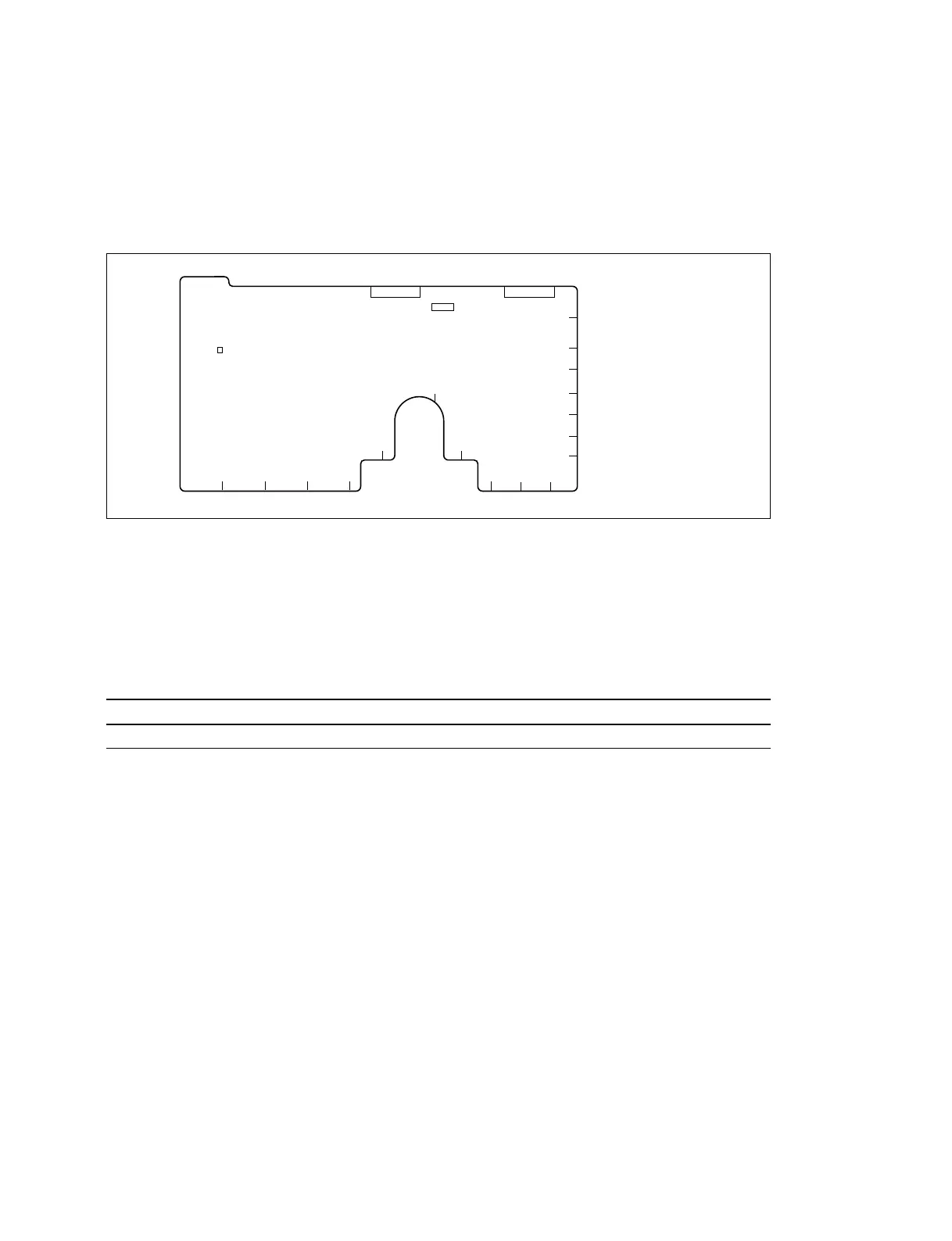
A side (Component side)
S1
S2
KJH CBA
7
6
5
4
3
2
1
8
GF ED
L
CN3 CN1
BKDM-3010
6-6. Description of Switches on Board
6-6. Description of Switches on Board
n
The address on the board is shown in the parentheses.
6-6-1. CPU-119 Board
Switch
S1 (L-6) : Reset switch
Resets the CPU on the CPU-119 board.
S2 (E-8) : Test switch
Factory setting :
S2-1 S2-2 S2-3 S2-4 S2-5 S2-6 S2-7 S2-8
ON ON ON ON OFF OFF OFF ON
S2-1 through S2-6 : CN3 test switch
S2-1 : Inputs RX-A signal to connector (CN3).
S2-2 : Inputs RX-B signal to connector (CN3).
S2-3 : Outputs TX-A signal from connector (CN3).
S2-4 : Outputs TX-B signal from connector (CN3).
S2-5 : Connects TX-B and RX-B signals internally.
Used for operation check.
S2-6 : Connects TX-A and RX-A signals internally.
Used for operation check.
S2-7, 8 : CN1 test switch
S2-7 : Connects TXD and RXD signals internally.
Used for operation check.
S2-8 : Inputs RXD signal to connector (CN1).