2-20
HDS-7150/7100
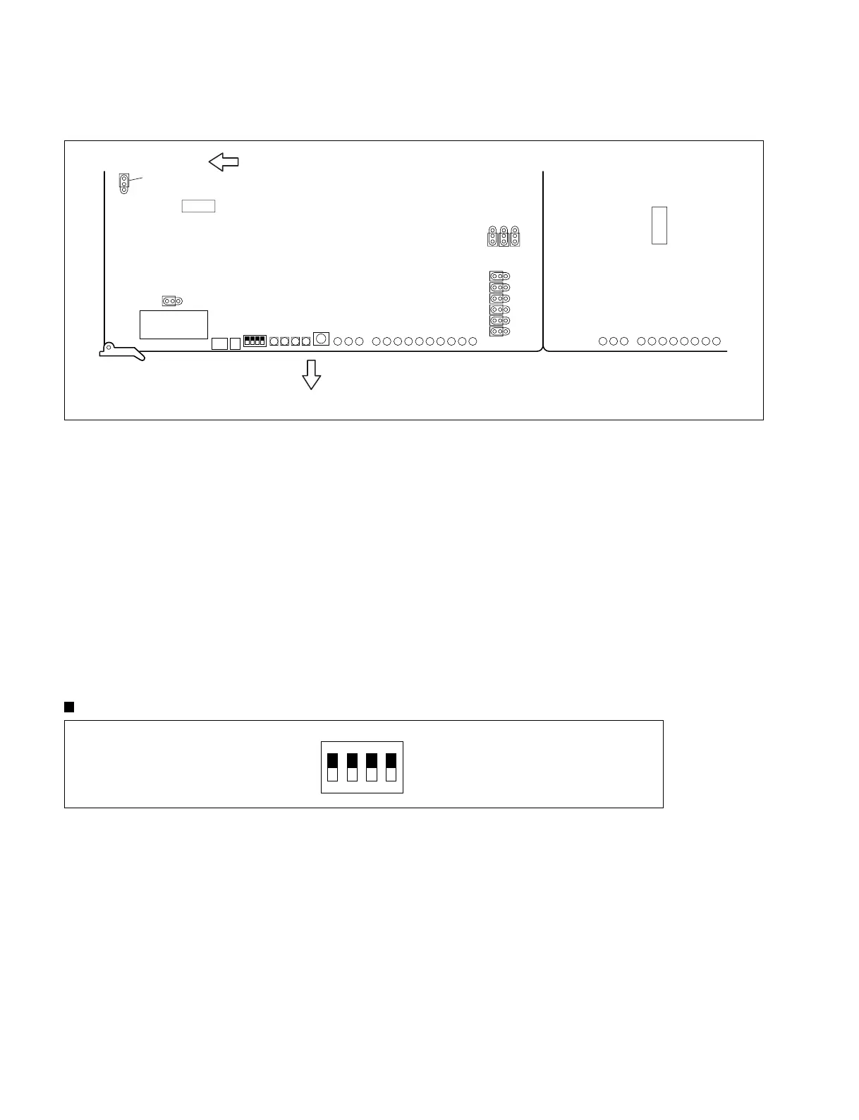
2-7-3. CPU-183 Board (HDS-7150/HDS-7100/HKDS-7071)
D1, D2 (Q-4), D3, D4, D8 (Q-5), D9, D10, D11, D12, D13, D14, D15, D16, and D17 (Q-6) :
Operating status indication
These LEDs are used for the factory setting.
COP1 (J-1), COP3, COP4, COP5 (M-7), COP6 (P-2), COP7, COP8, COP9, COP10 (P-7),
COP11, and COP12 (Q-7) : Mode setting connector pin
These jumpers are used for the factory setting. Connect the pin headers for normal operation as shown in
the figure above.
S1 (Q-4) : Mode setting switch
This switch is used for the factory setting. Set all knobs to ON position for normal operation.
n
indicates the knob position.
S2 (Q-5) : RESET switch
Use the RESET switch to re-start forcibly the system by means of hardware. When this switch is pressed,
the HDS-7150/7100 perform the same operation as the power-on sequence. However, the resume
function is not operated.
CN8 (Q-2), CN9 (Q-3), and CN10 (Q-4) : Connectors for the factory setting
These connectors are used for the factory setting.
ON
1234
A side (Component side)
HDS-7150/7100
2-7. Description of Switches and LEDs on Boards
COP1
COP2
CN5
COP6
COP3
COP4
COP5
COP7
COP8
COP9
COP10
COP11
COP12
CN8
CN9
CN10
D1
D2
D3
D4
D5
D6
D7
D13
D14
D15
D8
D9
D10
D11
D12
D13
D14
D15
D16
D17
D16
D17
D18
D19
D20
D21
D22
D23
S1
S2
1
2
3
4
ON
ACT 12 V 5 V 3 V
VD
1 2 3 4 5 6 SON SLV MAS IOT VCC VDD VEE
Top side
1
1
1
1
Pin header
Front side



 To Next Page