6-3
HDS-7150/7100
BKDM-3010
6-4. Input and Output Signals of Connectors
6-4. Input and Output Signals of Connectors
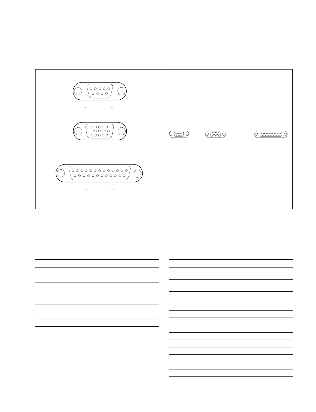
The input and output signals of the connectors on the rear panel are specified in the following table. And
refer to the following illustration for the pin positions of the connectors.
MONITOR :
RGB output (D-sub 15-pin, Female, 3 LINES)
Pin No. Signal Name Function
1 R Red output
0.714 V p-p (±10%) /75 Z
2 G Green output
0.714 V p-p (±10%) /75 Z
3 B Blue output
0.714 V p-p (±10%) /75 Z
4 GND Ground
5 __
6 GND Ground
7 GND Ground
8 GND Ground
9 __
10 GND Ground
11 GND Ground
12 __
13 H sync H sync output (TTL level)
14 V sync V sync output (TTL level)
15 __
n
<CONTROLLER> indicates a controlling device.
<DEVICE> indicates a controlled device.
SPARE : RS-232C (D-sub 9-pin, Male)
<CONTROLLER> to Mouse or ISR
Pin No. Signal Name Function
1 __
2 TXD Transmitted data
3 RXD Received data
4 DTR Data terminal ready
5 SG Signal ground
6 __
7 RTS Request to send
8 __
9__
15
69
EXT VIEW
[D-sub 9-pin, Male]
13 1
25 14
EXT VIEW
[D-sub 25-pin, Female]
Pin position Rear panel
51
15 11
10 6
EXT VIEW
[D-sub 15-pin, Female, 3 LINES]
SPARE MONITOR PROCESSOR