7-2
HDS-7150/7100
7-1-1. Installation Slot of Plug-in Boards
The HDS-7150/7100 can be used for various systems, and its functions can be extended by selecting the
optional boards.
Each plug-in board must be installed in the corresponding slot of the HDS-7150/7100. Confirm that all
the boards are in the specified slots.
For the details of how to install the plug-in board, refer to Section 7-1-3.
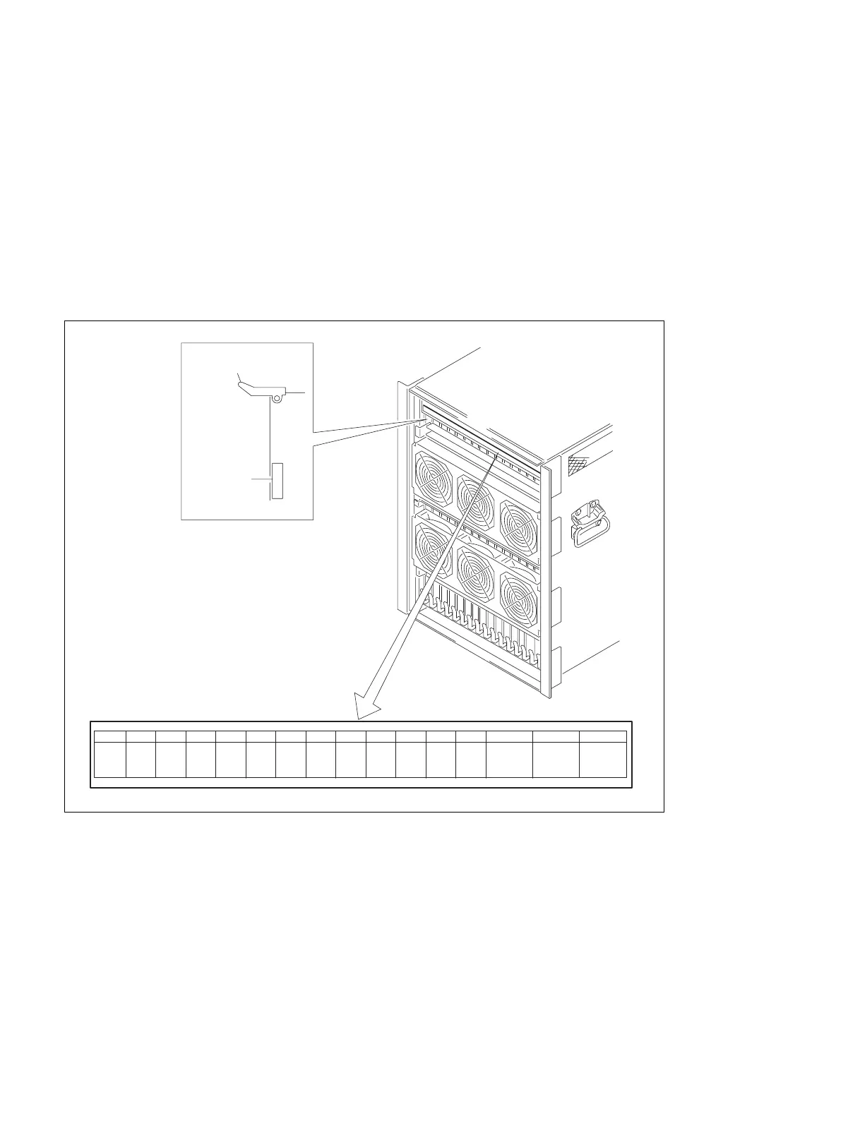
The board name are displayed near the eject lever at the left side on the A side (component side) of each
plug-in board. The slot number and a name of the plug-in board to be installed in the slot are indicated at
the upper side of the chassis in the HDS-7150/7100. Each optional board should also be installed at the
specified slot according to the slot number as well as the standard board.
m
. If the board is installed in an incorrect slot, a system error occurs. Then the system is not properly
activated.
. Be sure to confirm the power supply voltage when an optional board is added or a board is replaced.
(Refer to “Section 8 Adjustment of Secondary Power Supply Voltage”.)
7-1. Installation of Options for HDS-7150/7100
CPU-183
1234
5
910111213 14 15 16678
CPU-183
VSE-19 DLP-17
CPU-183
MPU-111
CRK-9 KPC-15
WKG-29
VSW-66
CCR-1827
DSK-16 DI-37 OUT-20MEM-65
(Y)
MEM-65
(C)
MEM-65
(K)
CKG-26
VSE-20 VSE-21 MIX-43
Eject lever
Board name
A side (component side)