6-4
HDS-7150/7100
PROCESSOR : RS-422A (D-sub 25-pin, Female)
<CONTROLLER> to HDS-7150/7100 etc.
Pin No. Signal Name Function
1 FG Frame ground
2 POWER +12 V input
3 RX-A Received data (_)
4 GND Common ground
5 TX-A Transmitted data (_)
6 __
7__
8__
9 VD-A Received VD signal (_)
10 GND Common ground
11 __
12 GND Common ground
13 GND Common ground
14 POWER +12 V input
15 POWER +12 V input
16 RX-B Received data (+)
17 GND Common ground
18 TX-B Transmitted data (+)
19 __
20 __
21 __
22 VD-B Received VD signal (+)
23 __
24 __
25 FG Frame ground
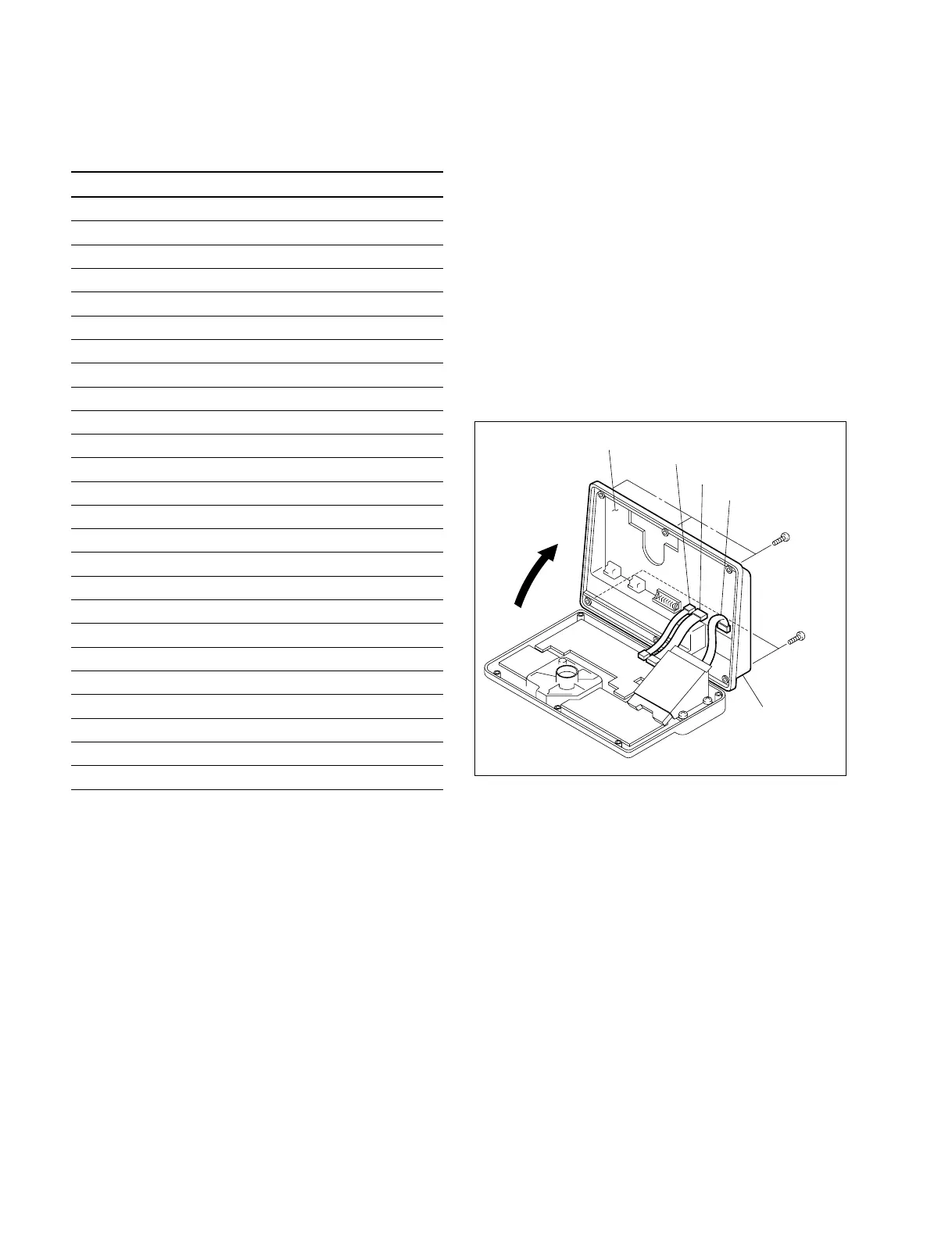
6-5. Removal of Bottom Panel
(1) Turn BKDM-3010 upside down.
(2) Remove the six screws shown in the figure, then open
the bottom panel in the direction indicated by the
arrow.
n
Pay attention to the direction when opening the bottom
panel.
Do not open it in the reverse direction. Connectors are
caught on the bottom panel.
(3) Disconnect the three connectors (CN4, CN5 and CN6)
on the CPU-119 board, then remove the bottom panel.
CN4
CN5
CN6
BVWH3 x 8
BVWH3 x 8
Bottom panel
CPU-119 board
BKDM-3010
6-4. Input and Output Signals of Connectors
6-5. Removal of Bottom Panel