STR-DA2800ES
137
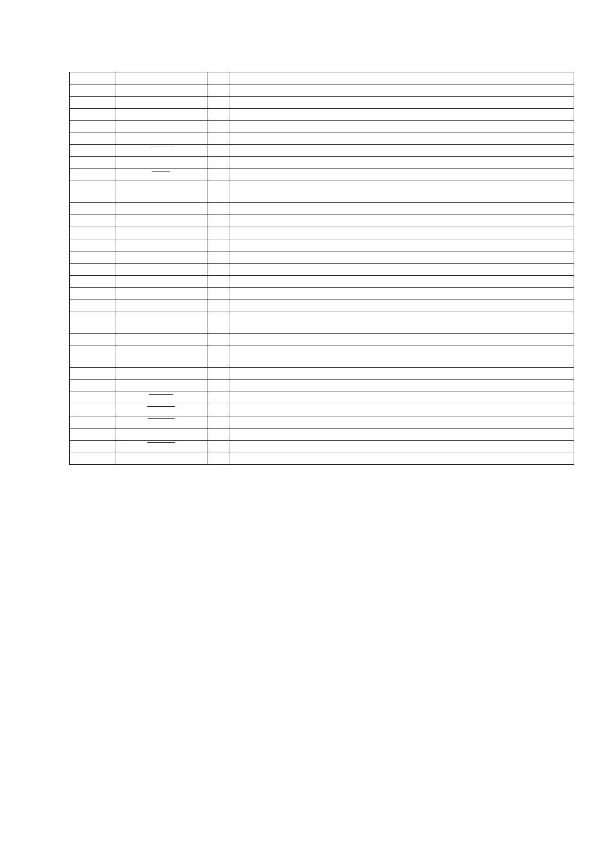
Pin No. Pin Name I/O Description
139 MLBDAT I Not used
140 MLBDO I Not used
141 VDD_EXT - Power supply terminal (+3.3V) (for I/O)
142 MLBSIG I Not used
143 VDD_INT - Power supply terminal (+1.2V) (for core)
144 TRST
I Test reset signal input terminal (for JTAG) Not used
145 MLBSO I Not used
146 EMU
O Emulation status signal output terminal Not used
147 to
150
DATA0 to DATA3 I/O Two-way data bus with the SD-RAM
151 TDO O Test data output terminal (for JTAG) Not used
152 DATA4 I/O Two-way data bus with the SD-RAM
153 VDD_EXT - Power supply terminal (+3.3V) (for I/O)
154, 155 DATA5, DATA6 I/O Two-way data bus with the SD-RAM
156 VDD_INT - Power supply terminal (+1.2V) (for core)
157 DATA7 I/O Two-way data bus with the SD-RAM
158 TDI I Test data input terminal (for JTAG) Not used
159 SDCLK O Clock output to the SD-RAM
160 VDD_EXT - Power supply terminal (+3.3V) (for I/O)
161 to
163
DATA8 to DATA10 I/O Two-way data bus with the SD-RAM
164 TCK I Test clock signal input terminal (for JTAG) Not used
165 to
168
DATA11, DATA12,
DATA14, DATA13
I/O Two-way data bus with the SD-RAM
169 VDD_INT - Power supply terminal (+1.2V) (for core)
170 DATA15 I/O Two-way data bus with the SD-RAM
171 SDWE
O Write enable signal output to the SD-RAM
172 SDRAS
O Row address strobe signal output to the SD-RAM
173 RESET
I Reset signal input from the main system controller “L”: reset
174 TMS I Test mode selection signal input terminal (for JTAG) Not used
175 SDCAS
O Column address strobe signal output to the SD-RAM
176 VDD_INT - Power supply terminal (+1.2V) (for core)