Version 5.2 Sourcefire 3D System Installation Guide 124
Hardware Specifications
Sourcefire Defense Centers
Chapter 6
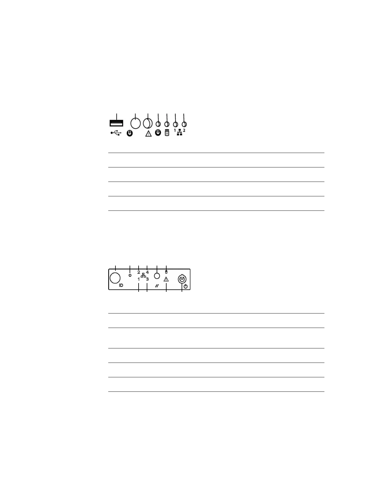
The following diagram illustrates the front panel controls and LEDs for the DC750
(Rev 1).
DC750 (Rev 1)
The following diagram illustrates the front panel controls and LEDs for the DC750
(Rev 2). The hard disk drive and system status icons, the numbers for the NIC (1,
2, 3, and 4) activity status, and the power button are also the LEDs.
DC750 (Rev 2)
Front Panel Components (Rev 1)
A USB port E Fixed disk drive status LED
B Power button F NIC 1 activity status LED
C System status LED G NIC 2 activity status LED
D Power LED
Front Panel Components (Rev 2)
A ID button with ID LED F Hard disk drive status LED
B Non-maskable interrupt
button
G NIC 1 activity status LED
C NIC 2 activity status LED H NIC 3 activity status LED
D NIC 4 activity status LED I System status LED
E Reset button J Power button with power LED