Version 5.2 Sourcefire 3D System User Guide 249
Power Requirements for Sourcefire Devices
3D8120/8130/8140 and 3D8250/8260/8270/8290
Appendix A
Grounding/Earthing Requirements
The Sourcefire 3D System must be grounded to the Common Bonding Network.
Bonding Locations
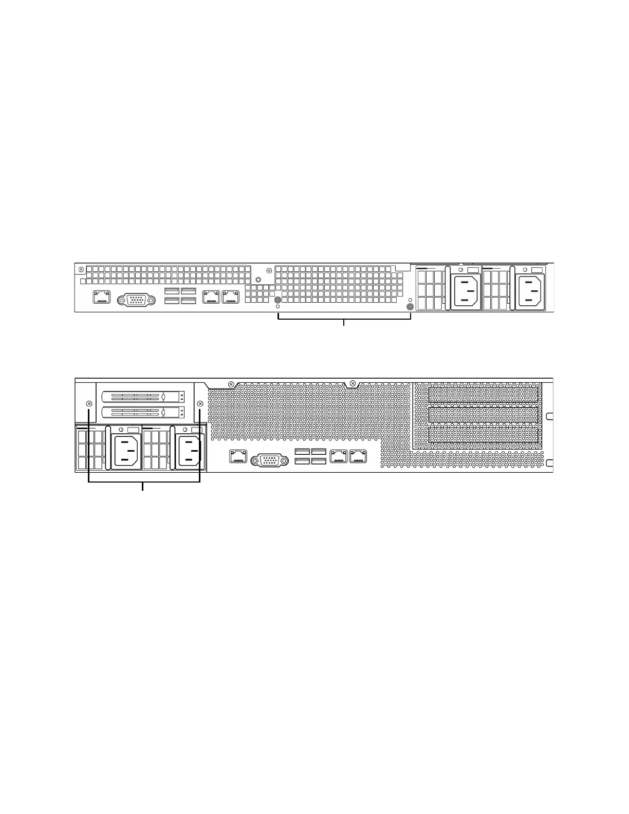
Ground bonding locations are provided on the rear of the chassis. M4 studs are
provided. Outside-toothed lock washers are provided for attaching ring terminals.
A standard ground symbol is available by each stud.
The following illustration indicates the bonding locations on the 1U chassis.
The following illustration indicates the bonding locations on the 2U chassis.
Recommended Terminals
You must use UL-Approved terminals for the ground connection. Ring terminals
with a clearance hole for 4mm or #8 studs may be used. For 10-12 AWG wire,
Tyco 34853 is recommended. This is a UL-approved, ring terminal with a hole for a
#8 stud.
Ground Wire Requirements
The ground wire must be sized sufficiently to handle the current of the circuit in
case of a single fault. The size of the ground wire should be equal to the current
of the breaker used to protect the circuit. For AC circuits, see
Current on
page 241. For DC currents, see DC Current on page 248.
Bare conductors must be coated with antioxidant before crimp connections are
made. Only copper cables can be used for grounding purposes.