Version 5.2 Sourcefire 3D System User Guide 244
Power Requirements for Sourcefire Devices
3D7110/7120 and 3D7115/7125
Appendix A
Example: Both supplies are attached to the same 220V circuit. The maximum
draw from this circuit would be 5A, as stated on the label.
Voltage
The power supplies will work with these voltages: 100VAC to 240VAC nominal
(85VAC to 264VAC maximum). Use of voltages outside this range may cause
damage to the appliance.
Current
The labeled current rating for each supply is: 10A maximum over the full range,
per supply 5A maximum for 187VAC to 264VAC, per supply. Appropriate wire and
breakers must be used to reduce the potential for fire.
Frequency Range
The frequency range of the AC power supply is 47 Hz to 63 Hz. Frequencies
outside this range may cause the appliance to not operate or to operate
incorrectly.
Power Cords
The power connections on the power supplies are IEC C14 connectors and they
will accept IEC C13 connectors. A UL-recognized power cord must be used. The
minimum wire gauge is 16 AWG. The cords supplied with the appliances are 16
AWG, UL-recognized cords with NEMA 515P plug. Contact the factory about
other power cords.
Grounding/Earthing Requirements
The Sourcefire 3D System must be grounded to the Common Bonding Network.
Bonding Locations
Ground bonding locations are provided on the rear of the chassis. M4 studs are
provided. Outside-toothed lock washers are provided for attaching ring terminals.
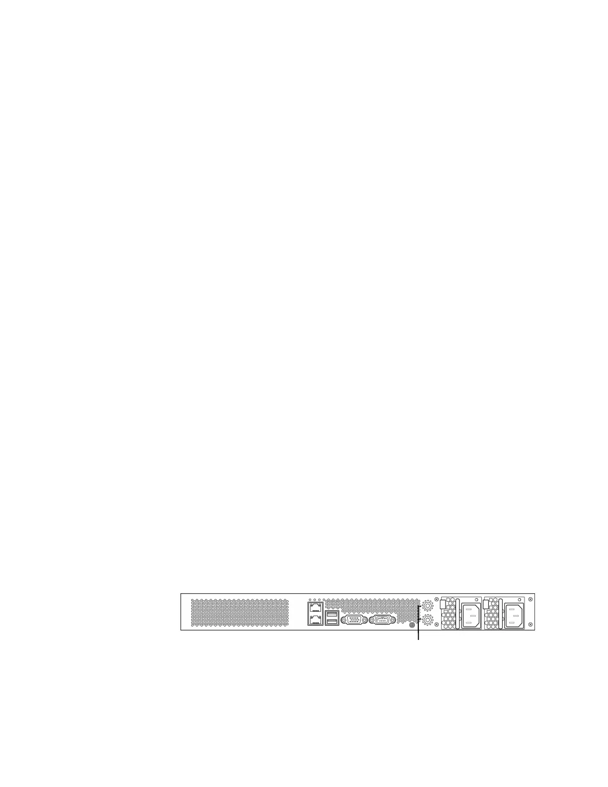
A standard ground symbol is available by each stud.
The following illustration indicates the bonding locations on the chassis.