Version 5.2 Sourcefire 3D System Installation Guide 62
Installing a Sourcefire 3D System Appliance
Identifying the Sensing Interfaces
Chapter 3
The following sections describe the sensing interfaces for each managed device.
For information on connection types, see
Understanding Interfaces on page 28.
• To locate the sensing interfaces on the 3D500/1000/2000, see Sourcefire
3D500/1000/2000 on page 62.
• To locate the sensing interfaces on the 7000 Series, see Sourcefire
7000 Series on page 63.
• To locate the module slots on the 8000 Series on the Sourcefire
8000 Series on page 67.
• To locate the sensing interfaces on the 8000 Series NetMods, see
8000 Series Modules on page 68.
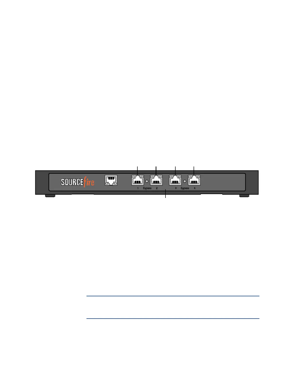
Sourcefire 3D500/1000/2000
The 3D500/1000/2000 is available as a desktop appliance. The following
illustration indicates the locations of the sensing interfaces.
You can use the sensing interfaces to passively sense up to four separate
network segments.
You also can use paired interfaces in inline or inline with bypass mode, which
allows you to deploy the device as an intrusion prevention system. The 3D500
can monitor one network when deployed inline, while the 3D1000 and 3D2000
can monitor two networks inline.
If you want to take advantage of the device’s automatic bypass capability, you
must connect either the two interfaces on the left (eth1 and eth2) or the two
interfaces on the right (eth3 and eth 4) to a network segment. This allows traffic
to flow even if the device fails or loses power. You must also use the web
interface to configure the interface set as inline with bypass.
If you configure the interfaces as inline without using the bypass capability, you
can use any two of the interfaces on the device as an inline pair.
IMPORTANT! By default, the initial setup process supports one inline bypass
interface pair for eth1 and eth2. For more information, see the Sourcefire 3D
System User Guide.
Sensing Interfaces
eth1 eth2 eth3 eth4