Version 5.2 Sourcefire 3D System Installation Guide 130
Hardware Specifications
Sourcefire Defense Centers
Chapter 6
DC1500 Chassis Front View
The front of the chassis contains the hard drives and the front panel controls.
The following diagram illustrates the front panel controls and LEDs.
The front panel of the chassis houses six LEDs, which you can view with or
without the front bezel to display the system’s operating state. The
DC1500 Front
Panel LEDs table describes the LEDs on the front panel.
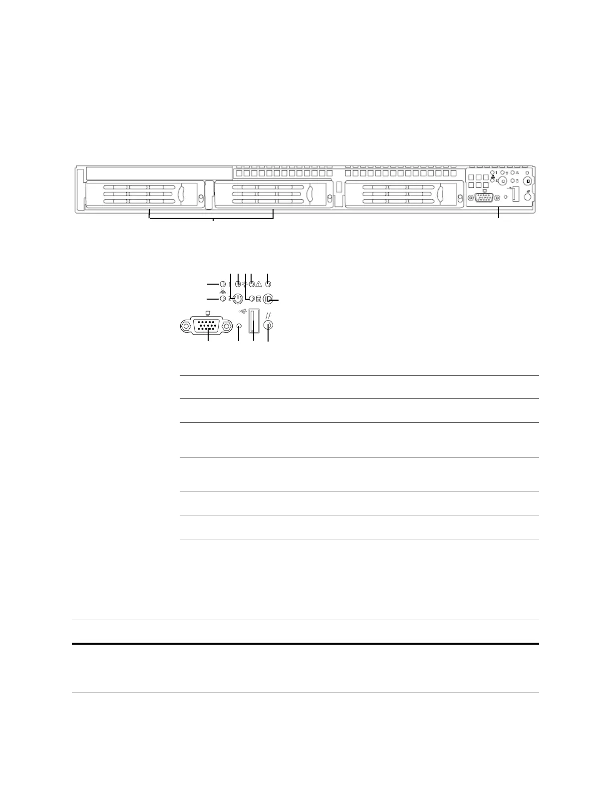
Front Panel ControlsHard Drives (RAID-1)
Front Panel Components
A NIC 2 activity LED G ID LED
B NIC 1 activity LED H ID button
C Power button I Video connector (not
available)
D Power/sleep LED J Non-maskable interrupt
button
E Fixed disk drive status K USB 2.0 connector
F System status LED L Reset button
DC1500 Front Panel LEDs
LED DESCRIPTION
NIC 1 activity
NIC 2 activity
Indicates activity between the system and the network:
• A blinking green light indicates activity.
• No light indicates no activity.