Version 5.2 Sourcefire 3D System Installation Guide 136
Hardware Specifications
Sourcefire Defense Centers
Chapter 6
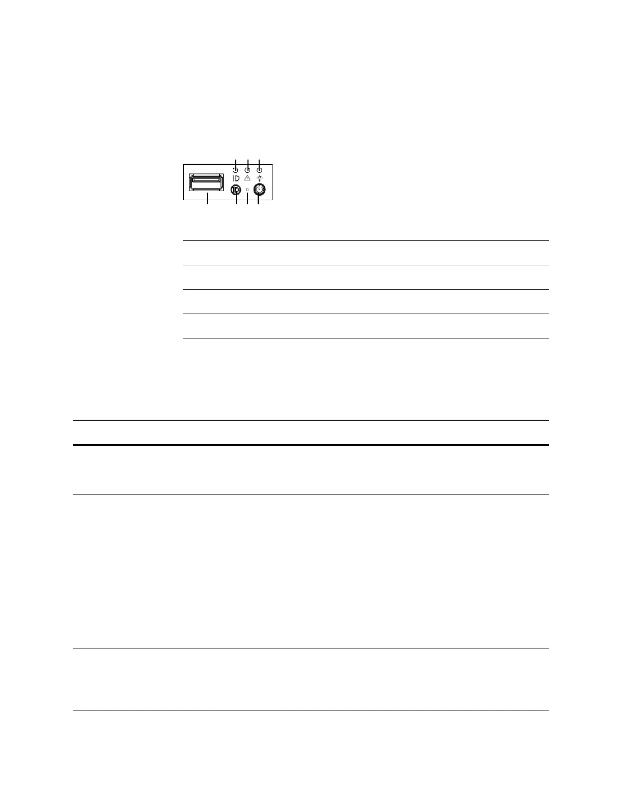
The following diagram illustrates the front panel controls and LEDs.
The front panel of the chassis houses three LEDs, which display the system’s
operating state. The
DC3500 Front Panel LEDs table describes the LEDs on the
front panel.
Front Panel Components
A ID LED E ID button
B System status LED F Reset button
C Power LED G Power button
DUSB port
DC3500 Front Panel LEDs
LED DESCRIPTION
Power Indicates whether the system has power.
• A green light indicates that the system has power.
• No light indicates the system does not have power.
System status Indicates the system status.
• A green light indicates the system is operating normally.
• A blinking green light indicates the system is operating in a degraded
condition.
• A blinking amber light indicates the system is in a non-critical condition.
• An amber light indicates the system is in a critical or non-recoverable
condition.
• No light indicates the system is starting up or off.
IMPORTANT! The amber status light takes precedence over the green status
light. When the amber light is on or blinking, the green light is off.
See the DC3500 System Status table on page 137 for more information.
Hard drive activity Indicates the hard drive status.
• A blinking green light indicates the fixed disk drive is active.
• An amber light indicates a fixed disk drive fault.
• No light indicates there is no drive activity or the system is powered off.