Version 5.2 Sourcefire 3D System Installation Guide 144
Hardware Specifications
Sourcefire Series 2 Devices
Chapter 6
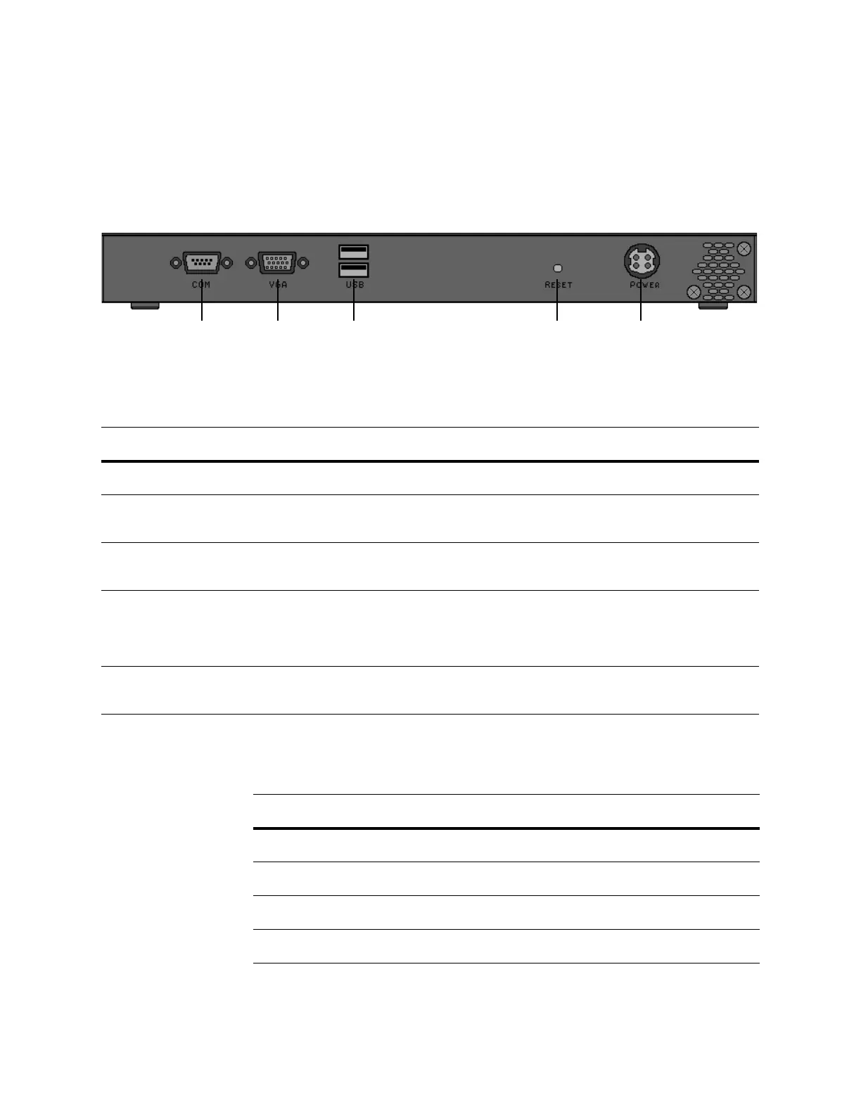
3D500, 3D1000, and 3D2000 Chassis Rear View
The rear of the chassis contains the connection ports and power supply.
The following table describes the features that appear on the rear of the
appliance.
.
The following table describes the signal present on the DB-9 connector.
Serial port VGA port USB port Reset button Power supply
3D500, 3D1000, and 3D2000 System Components: Rear View
FEATURE DESCRIPTION
Power supply Provides power to the appliance through an AC power source.
Serial port Allows you to establish a direct workstation-to-appliance connection. This
gives you direct access to all of the appliance’s management services.
VGA port Allows you to attach a monitor to the appliance, as an alternative to using the
serial port to establish a direct workstation-to-appliance connection.
USB ports Allows you to attach a monitor to the appliance, as an alternative to using the
serial port to establish a direct workstation-to-appliance connection. You must
also use a USB port to restore the appliance to its original factory-delivered
state, using the thumb drive delivered with the appliance.
Reset button Allows you to reboot the appliance without disconnecting it from the power
supply.
3D500, 3D1000, and 3D2000 Serial Port Pin Assignments
PIN SIGNAL DESCRIPTION
1 DCD Carrier detect
2 RD Received data
3 TD Transmitted data
4 DTR Data terminal ready