SPACE s.r.l.
Soc.a socio unico
PFB035 SERIES – PFB040 SERIES
PFB045 SERIES – PFB060 SERIES
SPRT102/4 SERIES – SPRT102/5 SERIES
SPRT102/6 SERIES – SPRT102/7 SERIES
Code M0247 - Ver.1.4
(09/2016)
SPACE s.r.l. – 10090 TRANA (TO) Via Sangano, 48
Tel. (+39) 011/ 934 40 300 – Fax (+39) 011/ 933 88 64
e-mail: info@spacetest.it - www.spacetest.com
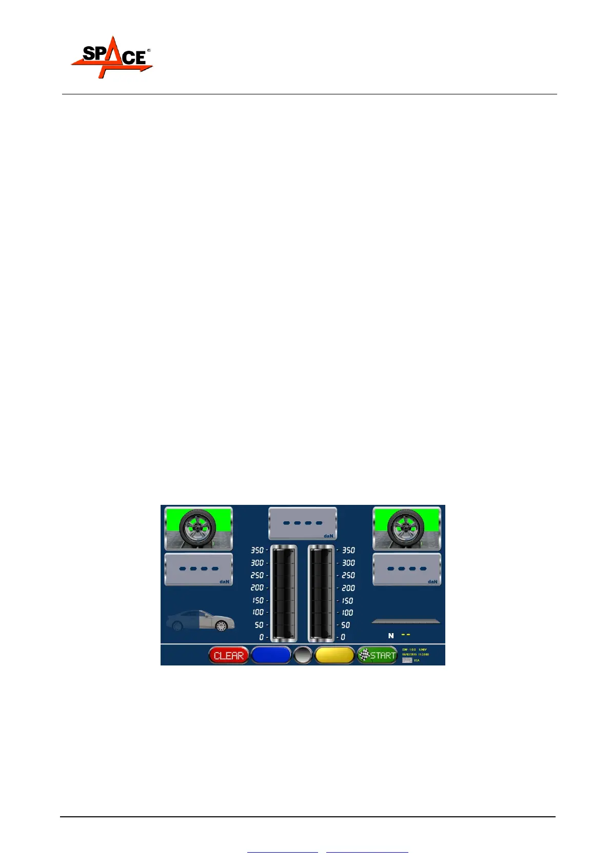
7.5. Brake test procedure
As suggested by the operating program (represented on the screen by a vehicle moving onto the
roller assembly), drive the vehicle onto the rollers with the remote control inside the vehicle and
the pedal pressure measuring device fitted on the brake pedal. The display page in Figure 49 will
appear.
The brake test performs the following measurements:
- Single wheel drag
- Brake ovality (out-of-roundness)
- Maximum brake force on wheels
- Braking unbalance between wheels of the same axle
- Braking efficiency of service, emergency and parking brakes
- Pressures applied to brake pedal and handbrake lever
The parking brake test is normally performed after testing the service brake of the rear axle and
is therefore automatically required by the system after this stage. The operator can however
manually select the parking brake test on the front axle as well before starting the rollers, by
means of the special key with the handbrake symbol. By means of the same key, the type of
parking brake can be selected: with hand-operated lever mechanism (normal setting) or pedal
operation (e.g. Mercedes).
NOTE: The parking brake test with hand-operated lever mechanism, which must be performed
with pedal pressure measuring device closed in the special sling, is automatically interrupted
when 40 daN is reached on the lever, while the parking brake test with pedal operation and service
brake test are interrupted at 50daN.
The brake tester can also be used for permanent four-wheel drive vehicles. In this case the 4WD
program must be selected by pressing the specific key.
The braking procedure is split into two stages for each axle being tested. During the first stage,
the left roller turns in the direction of vehicle movement and the right roller turns in the opposite
direction. During the second stage, the right roller turns in the direction of vehicle movement and
the left roller turns in the opposite direction; this uncouples the vehicle differential and prevents
transmitting torque to the axle off the rollers.
The results of the braking procedure are only available in the 4WD program when both stages
have terminated.
Figure 49
After engaging the roller assembly, the system is enabled to start the rollers and begin the braking
procedure; press START/F4 to start the rollers.
When the rollers are stopped the wheel symbols are green; when the rollers are started these
switch to red.
The end of test with consequently detection of braking effort at the roller stop it is caused by:
Slipping of one of the two wheels.
Stop by the remote control or keyboard from the user, by selecting the keys STOP or F1.
Reaching of threshold difference in 4WD mode.
 Loading...