4 Device description and operation
4.1 System block diagram
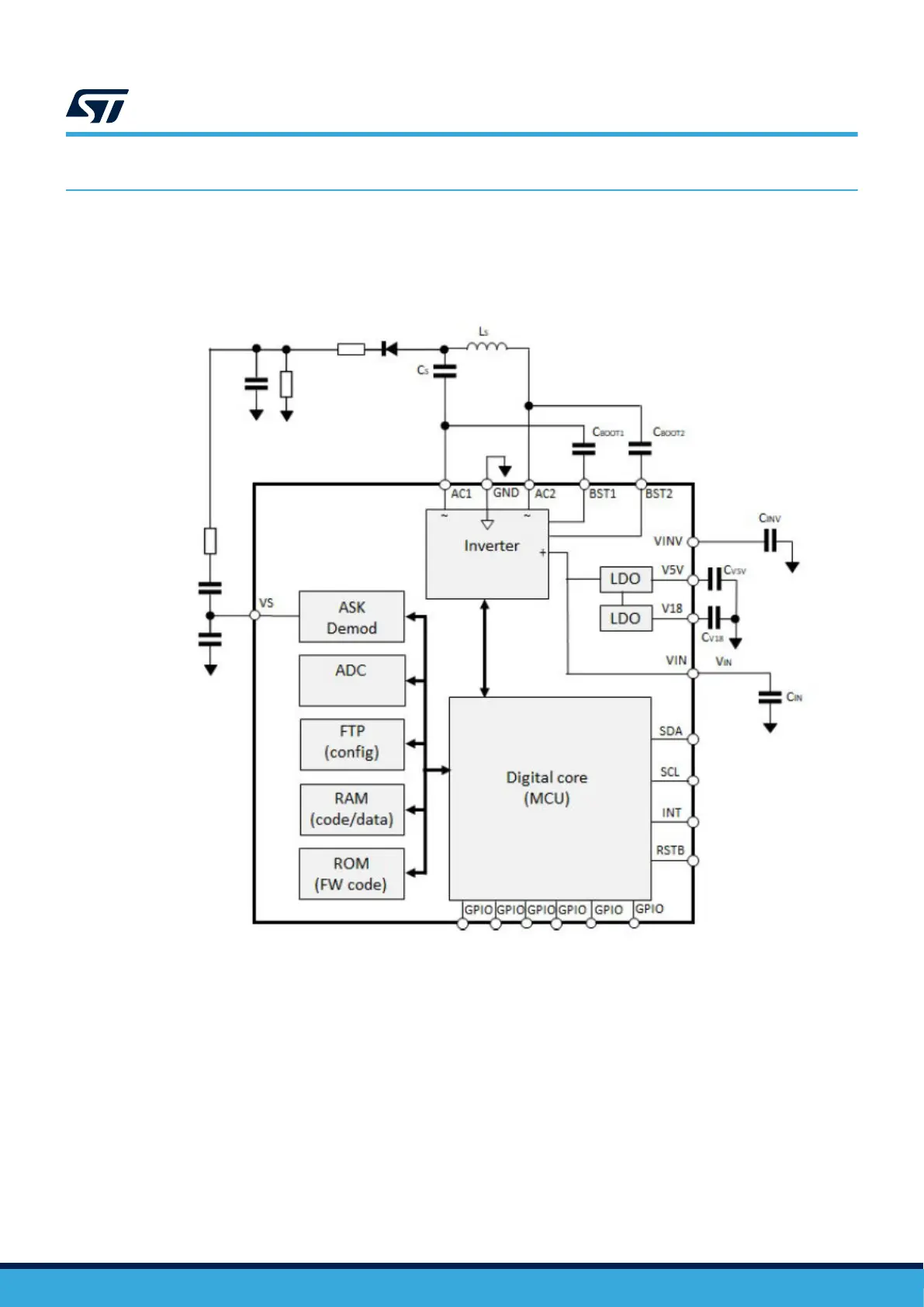
Figure 14. System block diagram
4.2 Integrated power inverter
The integrated power inverter is a key block in charge of converting the DC input into an AC power signal for the
transmitting coil. The power inverter consists of four N-channel MOSFET transistors arranged into a H-bridge,
conveniently driven by an internal control block, which also simultaneously monitors the key parameters of the
board to optimize switching and charging the external bootstrap capacitors for the high-side switches.
Some applications may require driving the power inverter in half-bridge mode – for example delivering a very
small amount of power might be difficult with some Tx/Rx coil combinations. The STWBC86 can be configured to
operate in half-bridge mode using the GUI.
UM3161
Device description and operation
UM3161 - Rev 1
page 15/78