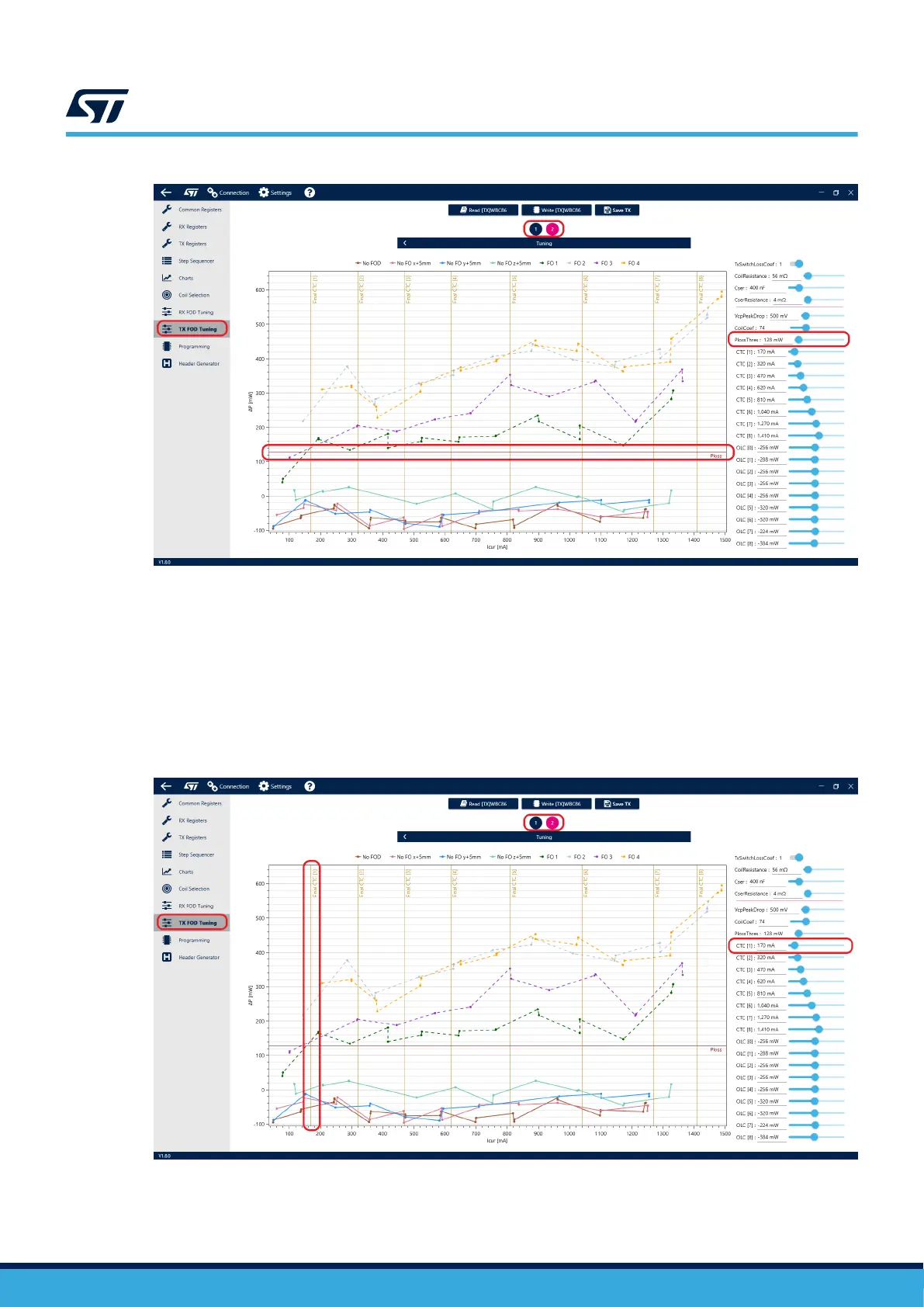
Figure 33. Ploss threshold
After adjusting all previously mentioned parameters, the curves can be further adjusted by setting power loss
offsets for selected input current intervals. Begin by defining the intervals using the CTC values. Those values
refer to the respective input current thresholds and are displayed as vertical lines in the plot. A unique offset can
be applied to every interval using the corresponding OLC slider. Please note that the first OLC value corresponds
to the interval ranging from zero input current to CTC [1], the second corresponds to interval “CTC [1] to CTC [2]”,
and so on, with the last OLC value corresponding to interval “CTC [8] and above”.
Remember, that the offsets adjust the relative position of ALL curves to the PlossThreshold, they cannot be used
to separate the FO and non-FO curves. Only VcpPeakDrop and CoilCoef can be used to separate the curves.
Figure 34. CTC threshold
UM3161
Foreign object detection (FOD)
UM3161 - Rev 1
page 27/78