6.2 Ring node voltage sensing
Ring node (the node between transmitting coil and series resonant capacitor) voltage measurement is used as an
additional indicator in foreign object detection. However, the DFT pin, used for the ring node voltage sensing, is
only 1.98 V tolerant. In addition, the internal ADC supports only up to a 1.5 V reading. A resistor divider is
therefore recommended to keep the DFT voltage below 1.5 V.
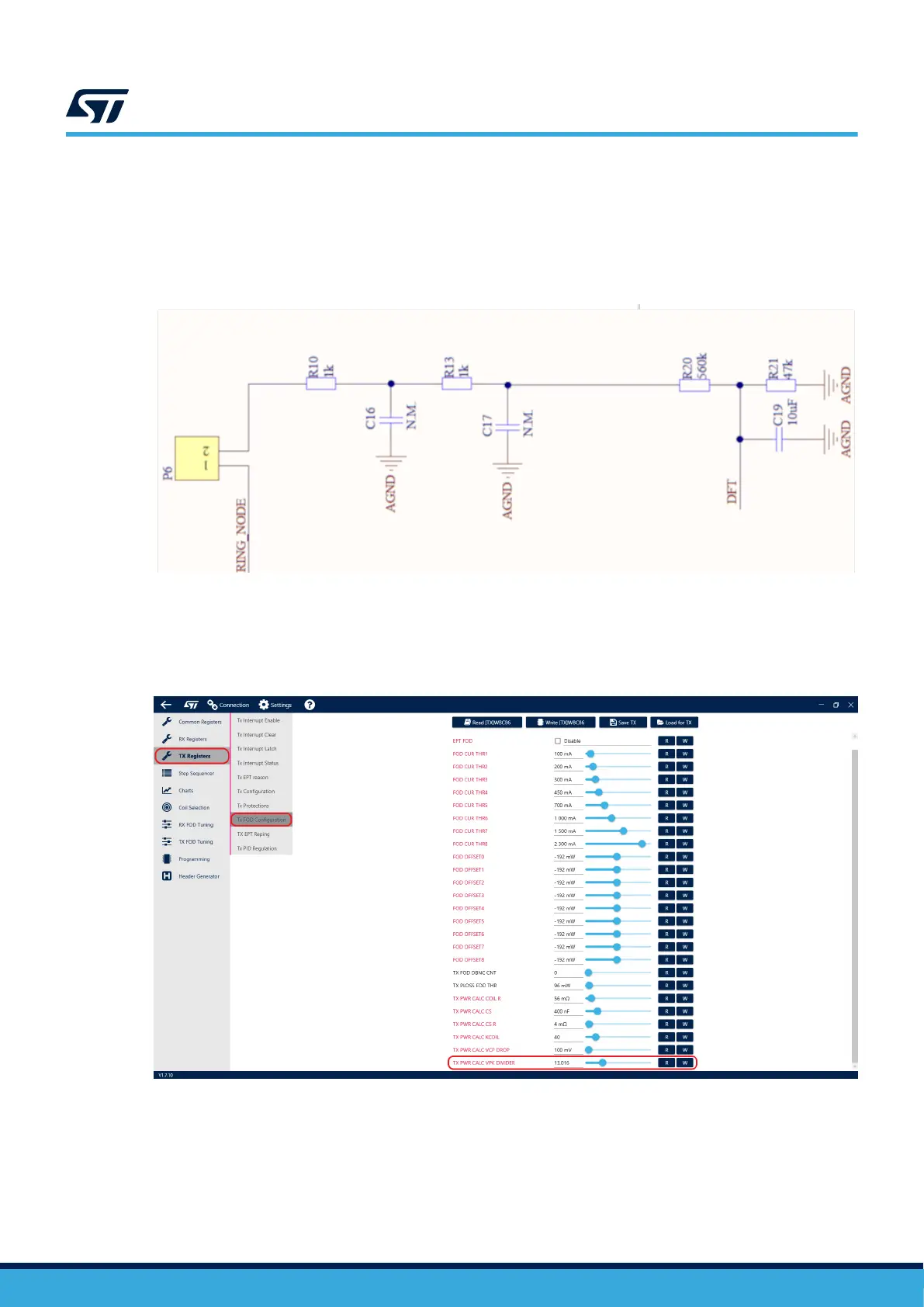
Figure 65. Ring node voltage sensing
To accurately measure the ring node voltage, the firmware requires the user to provide an accurate division factor
in the GUI. The corresponding setting can be found in the Tx FOD Configuration section of the TX Registers tab.
The division factor is defined as the ring node voltage divided by the DFT pin voltage.
Figure 66. Ring node divider configuration
6.3
PCB layout guidelines
• Power tracks (AC1, AC2, VINV, VIN) and power ground tracks should be kept wide enough to sustain high
current. Duplicating these tracks in inner layers and adding vias is advisable wherever possible to lower
impedance as much as possible.
UM3161
Ring node voltage sensing
UM3161 - Rev 1
page 51/78