96 EN
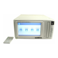
Figure 3: Removing the metal plate
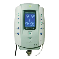
4. If jack screw posts are not present in the left (nine-pin) connector,
use the nut driver to insert the new jack screw posts (see
Figure
4).
Figure 4: Inserting jack screw posts
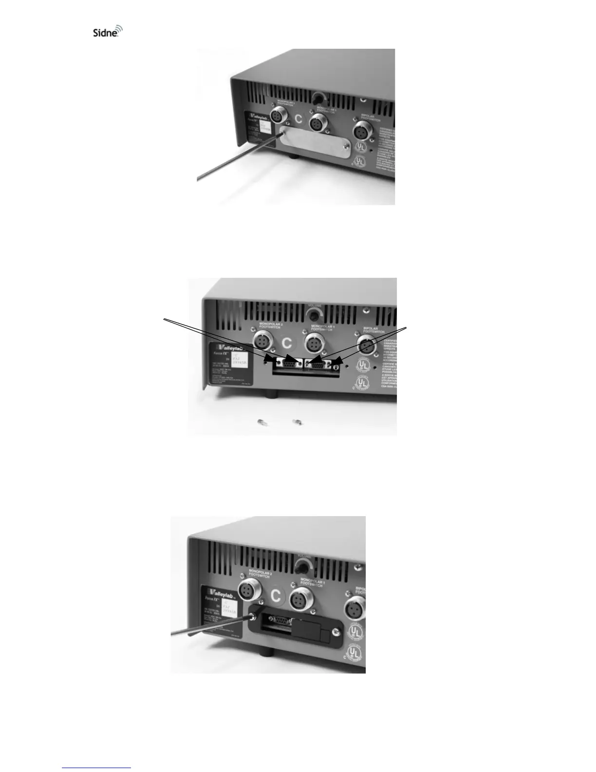
5. Place the new cover plate so that the opening allows access to
the ESU’s serial port (the nine-pin connector on the left). Replace
and secure the two screws (see
Figure 5).
Figure 5: Installing the new cover plate
Inserted jack
screw posts
Empty slots