Connecting the Electrosurgical Unit (ESU)
95 EN
Installing the Cover Plate
Ensure that the cover plate is mounted to the ESU before connecting to
Sidne™. If the cover plate is mounted, proceed to “
Connecting Sidne™ to
the Valleylab Force FX™ Electrosurgical Unit (ESU).” If the cover plate is
not mounted, continue with steps below.
Required Equipment
The following equipment is required to perform this procedure:
• Sharp knife
• Phillips head screwdriver
• Nut driver
Cover Plate Installation
1. Remove the cover plate from the interface kit.
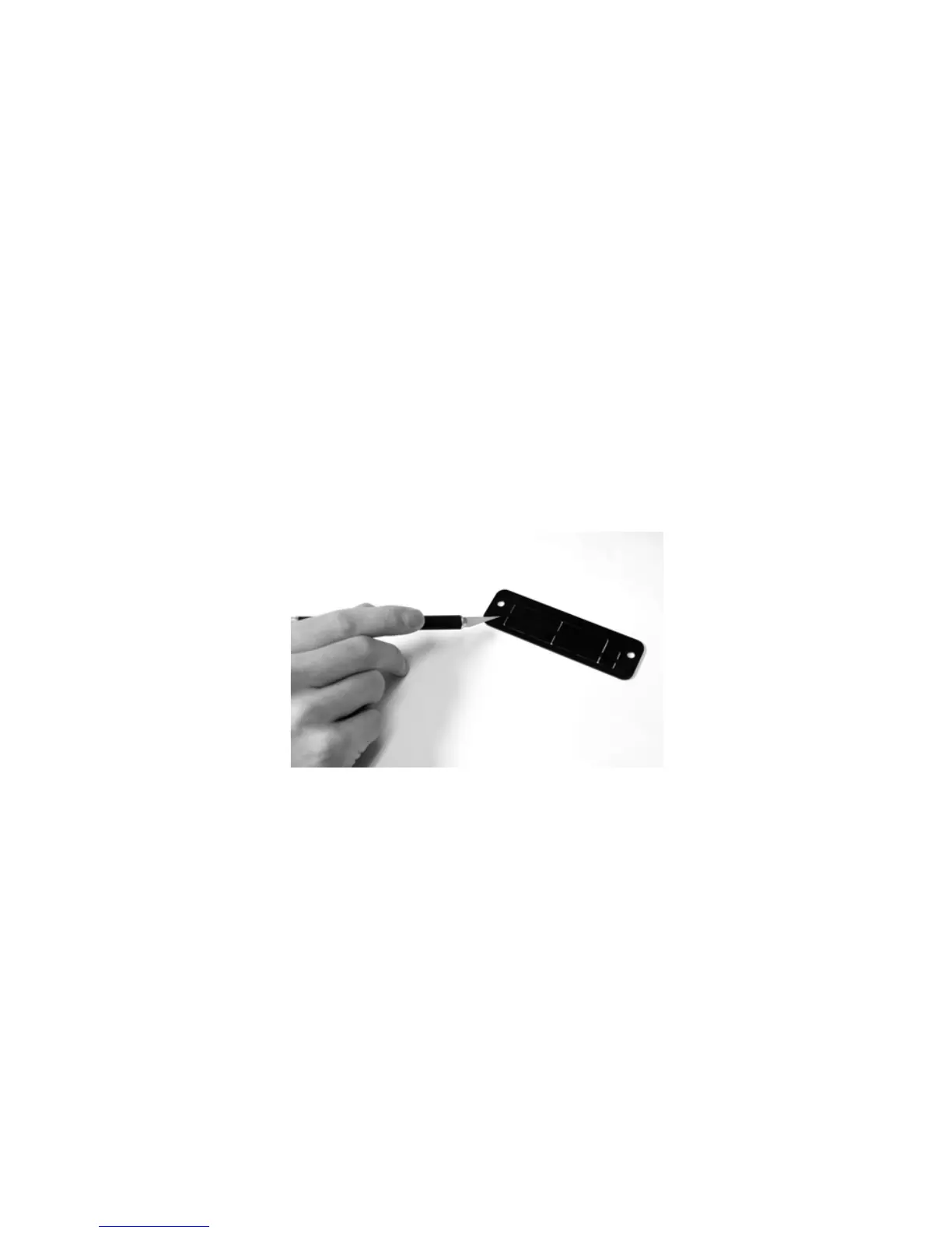
2. Using a sharp knife, cut out the serial port slot from the indented
side of the cover plate. The serial port slot is the rectangle on the
left (see
Figure 2).
Figure 2: Cutting the serial port slot from the cover plate
Note You may remove other panels from the cover plate if
necessary. The panels may also be pushed out by hand.
3. Remove the two screws that hold the metal plate covering the
ESU’s serial port. Remove the metal plate (see
Figure 3).