115
n > f • ( )
100
100 - nMax
(Z1)
nMax
/ %
n - Geräte
f = 1 f = 2 f = 3
60 3 5 8
65 3 6 9
70 4 7 10
75 4 8 12
80 5 10 15
85 7 14 20
90 10 20 30
© STULZ GmbH – all rights reserved EN/06.2019/G57
C7000 INSTRUCTIONS fOR A/C UNITS
6.2.2 CW Standby Management
Enabling the test sequencing (parameter in the fifth line of menu Z1) with the fixed cycletime of 5 minutes
helps you to check the sequencing function.
All basic zone functions which have been described on the previous pages are also available when the
sequencing is enabled.
a. Average value determination or deactivation
b. Alarm changeover
c. Emergency operation
d. Additional capacity
The sequencing runs independently from an additional capacity function and independently from defective
units.
Even a defective unit can be set standby by the sequencing. Only when the unit has to be switched on due
to the changeover, the control detects that the unit is defective and the unit remains switched off. Then the
standby unit with the next higher bus address is switched on.
The unit, which is provided as additional capacity, can only be switched on during the cycles, in which it is in
standby.
nMax
/ %
n - units
f = 1 f = 2 f = 3
The CW standby management can be carried out with CW units and
Dualfluid units with CW cooling priority. The basic idea is to share
the heat load permanently with as many as possible units in order to
reduce the fan speed of all units and thus to save energy. For this the
provided standby units must constantly take part in the cooling pro-
cess. The total airflow is below the airflow which is possible at most
and is equalled in case of failure of one or more units by increasing
the fanspeed of the remaining units.
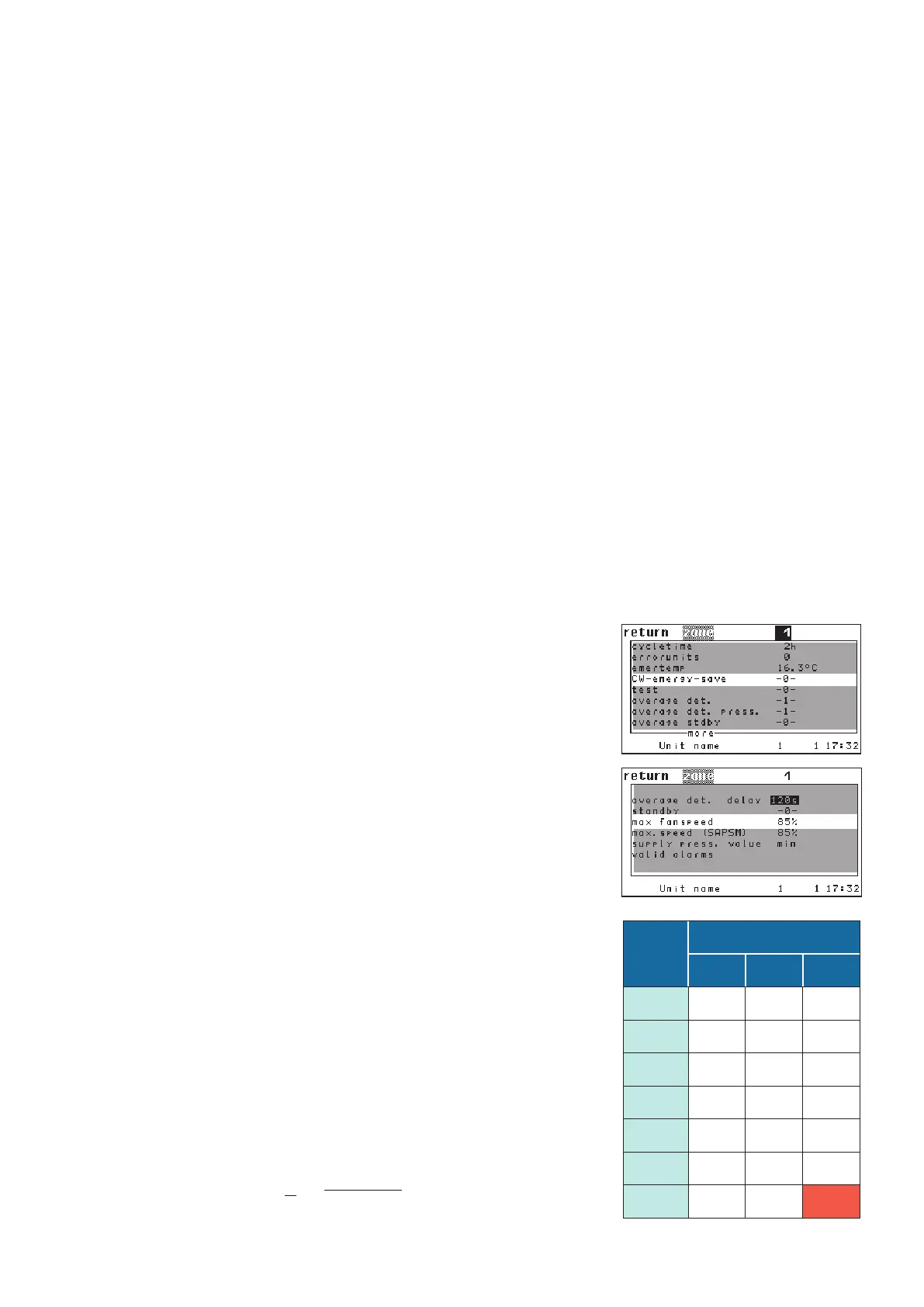
By "MAXFANSPEED" you adjust the fan speed which is to be kept
in the zone when all units are running. By "CWENERGYSAVE" the
CW-standby management is enabled and in the same moment all
standby units of the zone are switched on. Both parameters are
related to the zone and have only to be adjusted at one unit of the
zone.
The table beside displays how many units in a zone are necessary to
keep the total airflow at the indicated fan speed in the left column,
when "f" units have failed.
This correlation is represented by the following formula.