34
EC
TCE
PZHPSL
PZHPZH
TCE
TC
PI
PI
FS
TC
PSL
PC
PC
TC
pC
TC
pC
TC
TC
EEV
T/H C
EN/06.2019/G57 © STULZ GmbH – all rights reserved
C7000 INSTRUCTIONS fOR a/C UNITS
5. Configuration
First steps
1. When several units shall operate in a bus: Establish bus wiring and configure bus.
2. Check the equipment by command "equip".
3. Configure additional components like e.g. glycol pump, drycooler, outside temperature sensor.
At the C7000AT you can do this in the Config-level in the submenus of the menu point "Components". Part
of the configuration is the activation of the component, the allocation of an output for the component cont-
rol, the assignment of an alarm input and setting the start value / hysteresis.
4. Calibrate the sensors by reference instruments (menu Operate/Components/Sensor),
important for condensation pressure sensor.
5. Adjust setpoints.
6. Adjust special operating modes like week program, zone operation.
7. possibly BMS configuration
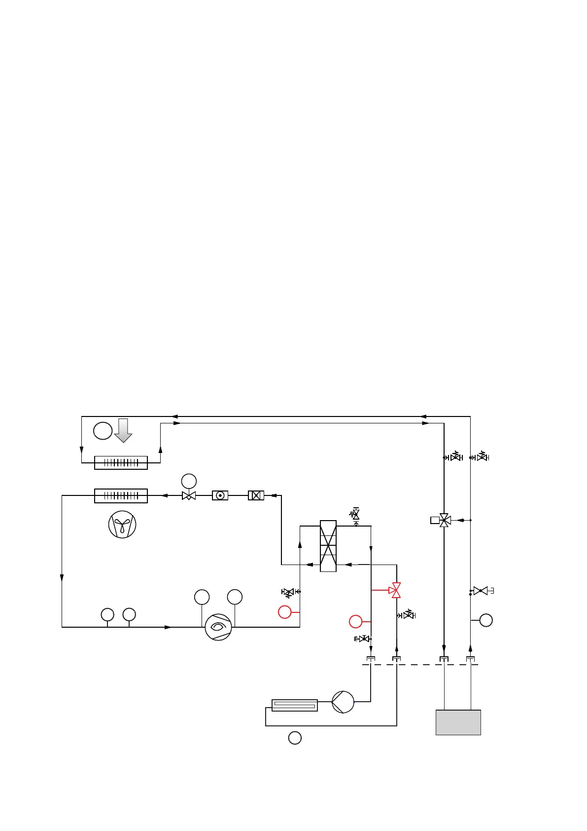
Compressor
Fan
Condenser
Evaporator
CW coil
Refrigerating scheme for a GCW type unit to localize the standard, optional and external components
Pump 3
Drycooler
Outside temp. sensor
External components are not part of the unit and
must be selected by the installer.
GE/CW
valve
WT1
inlet
WT2
outlet
G valve
HD switch
ND switch
press.
sensor
Temp.
sensor
for EEV
Chiller
Condensation
press. sensor
WT: water temperature
for malfunction
changeover with
"WT too high"
alarm
T/H sensor