157
Bus-
adr.
DIPSchalter
1 2 3 4 5
0 0 0 0 0 0
1 1 0 0 0 0
2 0 1 0 0 0
3 1 1 0 0 0
4 0 0 1 0 0
5 1 0 1 0 0
6 0 1 1 0 0
7 1 1 1 0 0
8 0 0 0 1 0
9 1 0 0 1 0
10 0 1 0 1 0
11 1 1 0 1 0
12 0 0 1 1 0
13 1 0 1 1 0
14 0 1 1 1 0
15 1 1 1 1 0
16 0 0 0 0 1
17 1 0 0 0 1
18 0 1 0 0 1
19 1 1 0 0 1
RS 485
56 57 58 59 56 57 58 59
LOW
HIGH
© STULZ GmbH – all rights reserved EN/06.2019/G57
C7000 INSTRUCTIONS fOR a/C UNITS
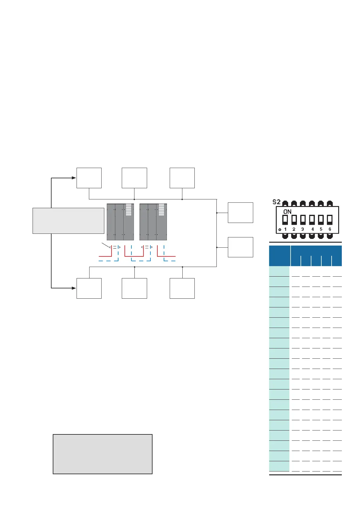
You need a shielded cable with two lines twisted and a cable impedance of 120 Ω (Recommendation Belden
9841), which you have to connect from unit to unit at the terminals 5659 of each C7000IOC. Connect the
screen only at one side of the cable.
In the example below the bus termination of the two units which form the end of the bus (addr. 01 and addr.
17) must be enabled.
The example of a RS485 bus shows an application with 8 bus participants.
7.3.4 Setting the Bus Address
Bus termination:
See description of the driver
module.
terminals
on IOC
terminals
on IOC
Screen
7.3.3 Preparation before Installation
bus
addr:
01
bus
addr:
03
bus
addr:
07
bus
addr:
08
bus
addr:
15
bus
addr:
18
bus
addr:
17
bus
addr:
14
Bus
addr.
DIP switches
1 2 3 4 5
The bus address is adjusted with the dip-switches on the C7000IOC. The table
at the right shows the corresponding adjustment for all possible bus address-
es. Please note that the counting begins with 0 and ends with 19. A "1" means
dip-switch in "ON"-position.
If you set an address higher than 19, this one is reduced to 19 by the software.
A C7000IOC is delivered with the address 1 as standard, a C7000AT has the
address 0 as standard.
On a C7000AT the bus address is adjusted in the placement view.
in short:
1. connect units by bus lines
2. set bus terminations (beginning/end)
3. adjust bus-IDs
4. confirm bus configuration