170
1 10 21 30 41 50
11 20 31 40 51 60
JP 2 3 4 5
JP 6
JP 7 JP 9 JP 8
OKLED
TX1LED
RX1LED
Error-LED
EN/06.2019/G57 © STULZ GmbH – all rights reserved
C7000 INSTRUCTIONS fOR a/C UNITS
10. Hardware components
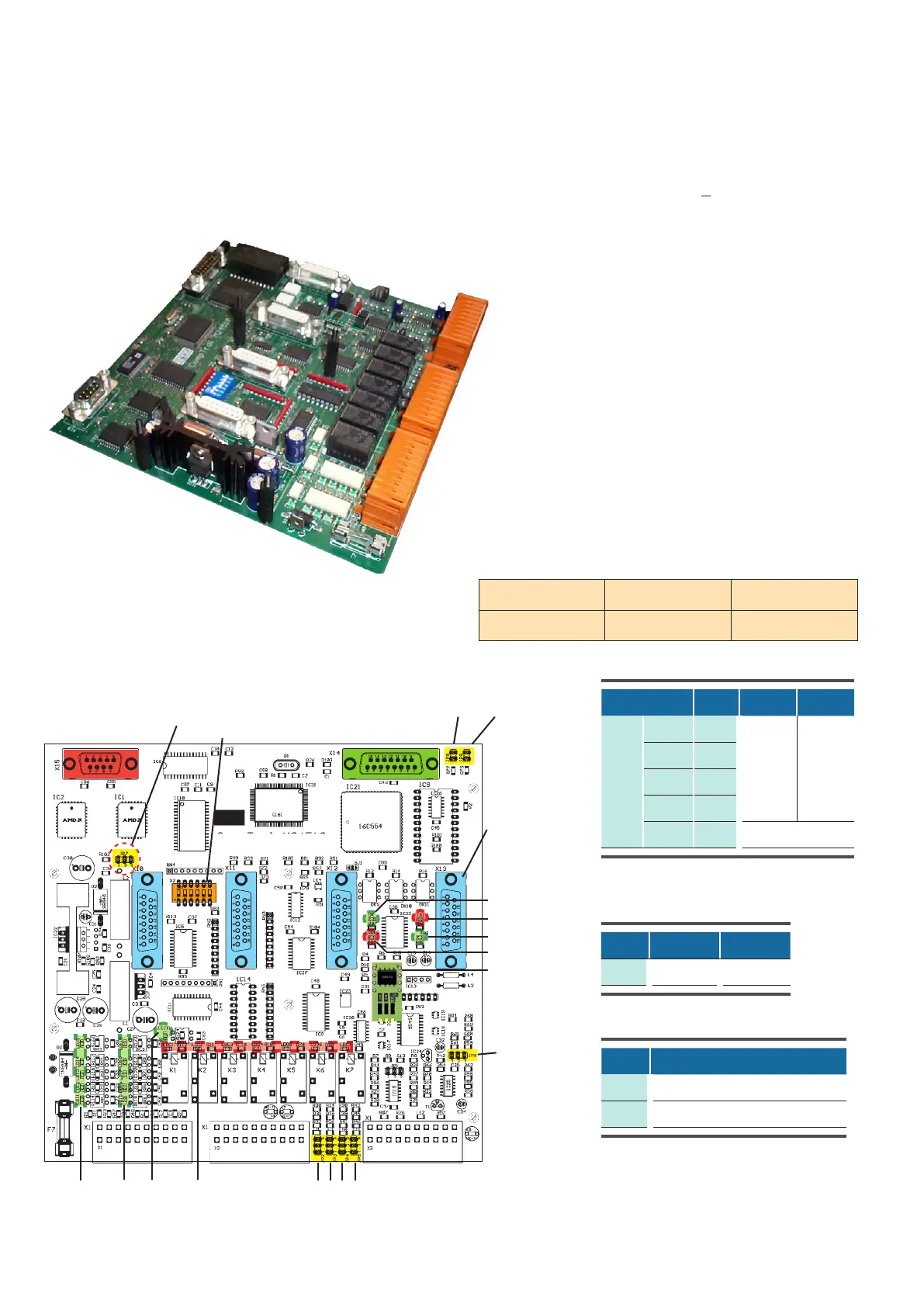
10.1 I/O controller (C7000IOC)
Pin position of X1
Service port
RS232
plug for EBUS ext.
board
green LEDs for red LEDs for
digital inputs 111 digital outputs 17
Onboard LEDs
The function of the digital inputs is displayed by green
LEDs:
ON: voltage present
OFF: no voltage (alarm, failure)
The function of the digital outputs is displayed by red LEDs:
ON: relay active
OFF: relay passive
The OKLED displays the IIC-bus clock. This is the pulse
for sensor evaluation too.
The TX1/RX1LEDs indicate data traffic on the I/O bus
(port 1).
The Error-LED lights up at any time, when an alarm has
occurred.
DIP-switches
for bus addr.
4 sockets for
EDIOs/EAIOs
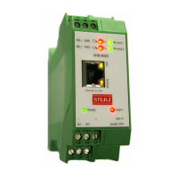
Bus driver module
for IO-bus
Technical Data:
Voltage supply: 24(+15%) V (AC)
Power consumption: 9,6 VA
Fuse: 2 A time-lag
Operating temperature: 5°C...40°C
Storage temperature: -30°C...60°C
Jp8 and Jp9 have to be set, if no EBUS
extension board is present. On the contrary,
it has to be removed to enable the extension
RS485 busses on a plugged EBUS extension
board.
Jumper setting depends on sensor types
Jp N° Pos. 12 Pos. 23
Analog input
AIN 1 2
420 mA
010 V
AIN 2 3
AIN 3 4
AIN 4 5
AIN 5 6 can not be used
EBUS activation
Jp N° Function, when set
8 EBUS Port 2 disabled
9 EBUS Port 3 disabled
Jumper for software download
Jp N° Pos. 12 Pos. 23
7 Operation Download