141 © STULZ GmbH – all rights reserved EN/06.2019/G57
C7000 INSTRUCTIONS fOR A/C UNITS
6.7 Differential temperature control
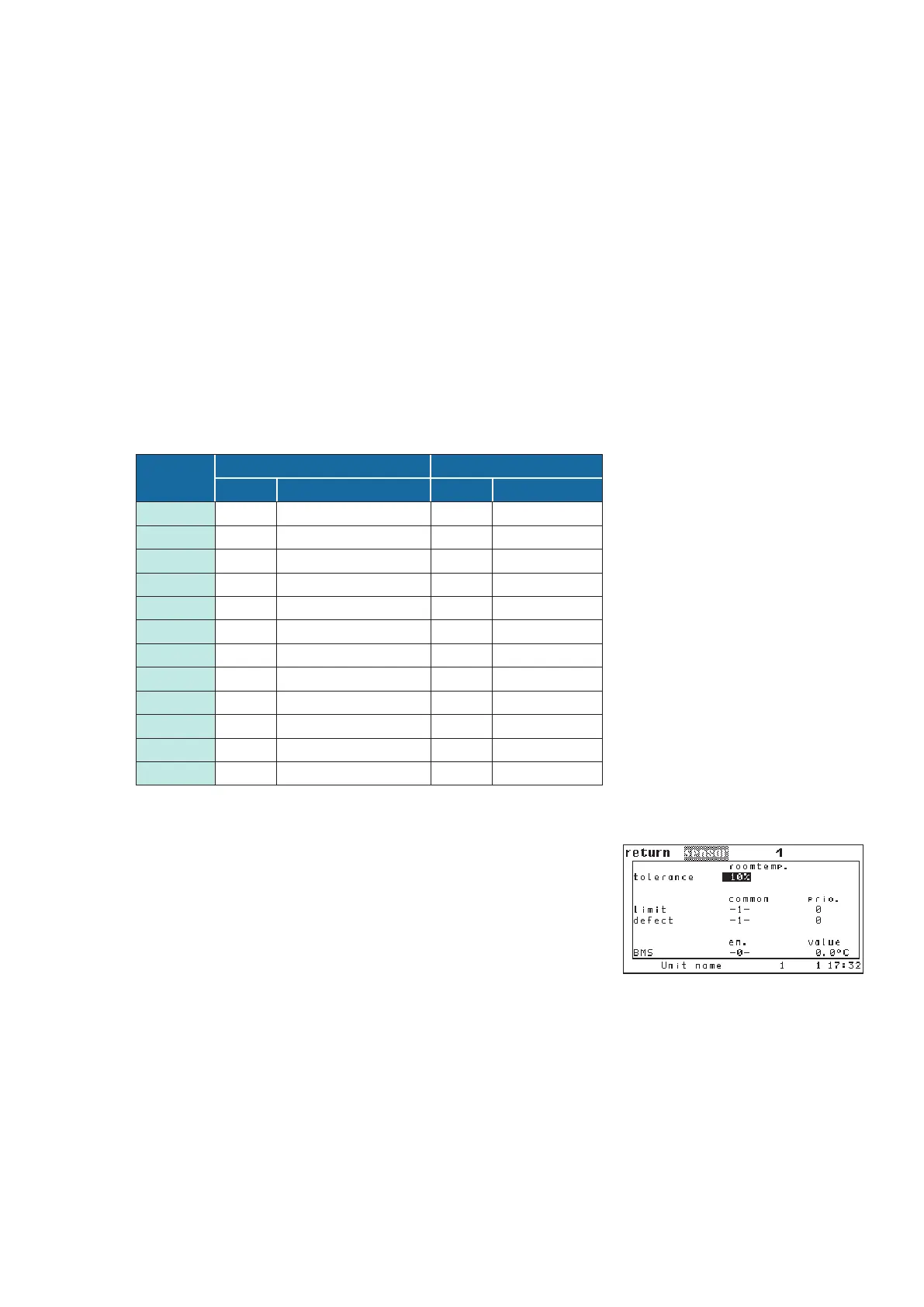
Due to different positions of the supply air temp. and return air temp.
sensors a deviation from the average of more than 10% (default) can
occur for the sensors 1, 3, 14 - 17, which then releases the alarm
"Sensor # excess".
To avoid this alarm, the admissible tolerance must be raised or set to
0%. At 0% the alarm is not evaluated.
Config/Components/Sensor
By the differential temperature control the speed of three fans can be separately controlled in dependance on
the temperature difference between return air and supply air temperature.
For this purpose three return air and three supply air temperature sensors are necessary, which must be pro-
vided with the sensor purposes: supply temperature 1, 2, 3 and room temperature 1, 2, 3.
Six further temperature sensors will only be installed on the level of the software, these use the same inputs
as the sensors first named and serve to calculate the average return air and supply air temperature, which are
used as actual values for the temperature control of the A/C unit.
Depending on the control mode - return air or supply air, with or without limitation - one or both values are
required for the temperature control.
The table below illustrates the assignment of analog inputs for a CyberRow ... GES unit:
Analog
input
real sensors virtual sensors
Sensor Sensor purpose Sensor Sensor purp.
AIN 1 8 Supply air temp. 1 3 Supply temp.
AIN 2 9 Supply air temp. 2 14 Supply temp.
AIN 3 10 Supply air temp. 3 15 Supply temp.
AIN 4 6 external temp. – –
AIN 5 – – – –
AIN 6 2 Room humidity – –
AIN 7 11 Room air temp. 1 1 Room temp.
AIN 8 12 Room air temp. 2 16 Room temp.
AIN 9 13 Room air temp. 3 17 Room temp.
AIN 10 5 Water inlet temp. 1 – –
AIN 11 4 Water outlet temp. 1 – –
AIN 12 7 Condensation press. 1 – –