179
{
© STULZ GmbH – all rights reserved EN/06.2019/G57
C7000 INSTRUCTIONS fOR a/C UNITS
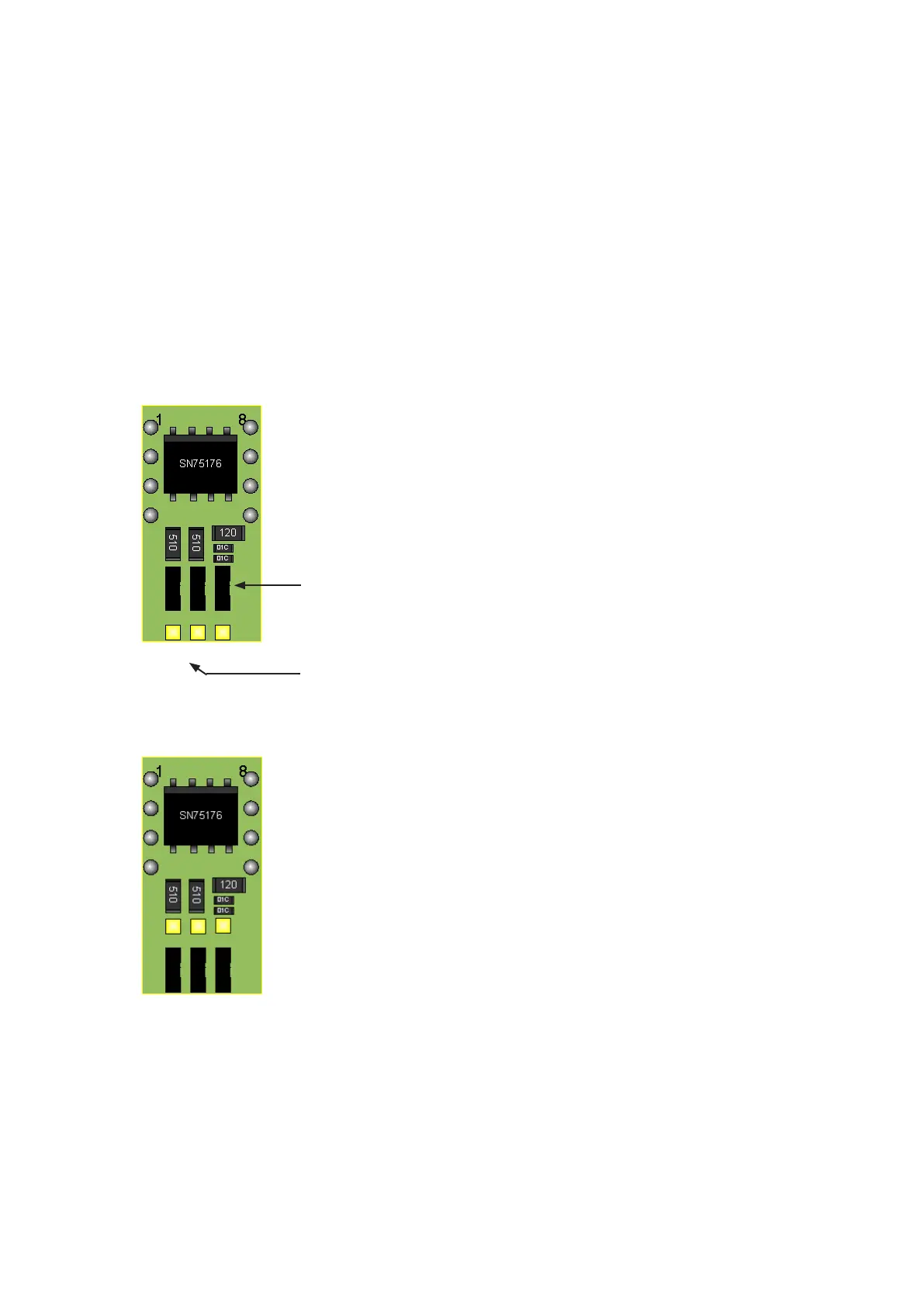
This figure shows the jumper position for the partici-
pant at the end of the bus.
The rightmost jumper is located in a position where the
termination resistor is activated.
The other jumpers are set for a high bias.
10.6.1 Driver module
Jumper to activate the termination resistance
Two jumpers to set the bias on the bus.
This figure shows the jumper position for the partici-
pant in the middle of the bus.
The rightmost jumper is located in a position where the
termination resistor is deactivated.
The other jumpers are set for a low bias.
The driver module has the following features:
1. a static bus termination (120 Ohm), which can be activated by a jumper.
2. a circuit to set the bias for the bus. By means of two jumpers either a low bias (bus middle) or a high bias (bus
end) can be set.
3. protection against electrostatic discharge (ESD) impulses on the data lines
The interference immunity of the bus is increased by the driver module.
As far as the jumper settings are concerned, only the two settings shown below are allowed. The jumpers must
be changed blockwise. Other settings result in an unstable bus communication.
Participant at the end of the RS485 bus
Participant in the middle of the RS485 bus