49 © STULZ GmbH – all rights reserved EN/06.2019/G57
C7000 INSTRUCTIONS fOR A/C UNITS
The dynamic condensation pressure control can be applied in A/C units of the G, GE, GCW and GS, GES,
GSCW version.
For each refrigerant circuit a condensation pressure curve can be set, according to which the condensation
pressure setpoint is calculated as a function of the measured evaporation pressure. The deviation of the
measured condensation pressure to the condensation pressure setpoint has an effect on the opening degree
of the G valve.
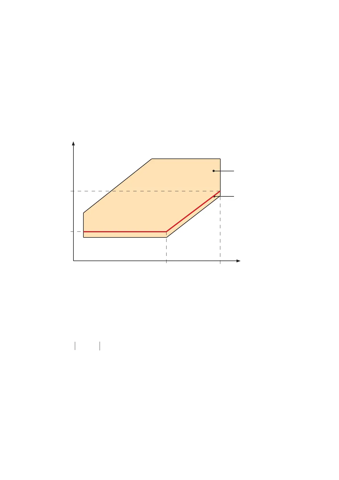
The condensation pressure curve is set by four parameters, which define two points of a straight line.
This straight line is optimally positioned such as it runs along the lower limit of the compressor operating zone.
Compressor operating zone
Evaporation pressure
Condensation pressure
operating zone
condensation pressure setpoint curve
By the following four commands you set the pressures, which determine the course of the condensation pres-
sure setpoint curve. The lower limit is set by cp1, the upper limit by cp2.
circuit 1
pressure value
By means of a further parameter the condensation pressure control is activated. This can be separately
set for each rerigerant circuit. So it is possible to run one refrigerant circuit with the dynamic condensation
pressure control, whereas the other refrigerant circuit runs with a fix condensation pressure setpoint.
Activation of dynamic condensation pressure control in circuit 1
Setting the fix condensation pressure setpoint for the mix mode in circuit 2
Setting the fix condensation pressure setpoint for the DX-mode in circuit 2
cp2
cp1
ep1
ep2
cpset 1 ep1 6,5
cpset 1 cp1 12,8
cpset 1 ep2 17,0
cpset 1 cp2 32,6
cpset 1 dyn 1
cpset 2 mix 12,3
cpset 2 dx 18,4