TIMING BELT ASSEMBLY
MECHANICAL
(6)
Ensure camshaft and crankshaft sprockets
are positioned properly.
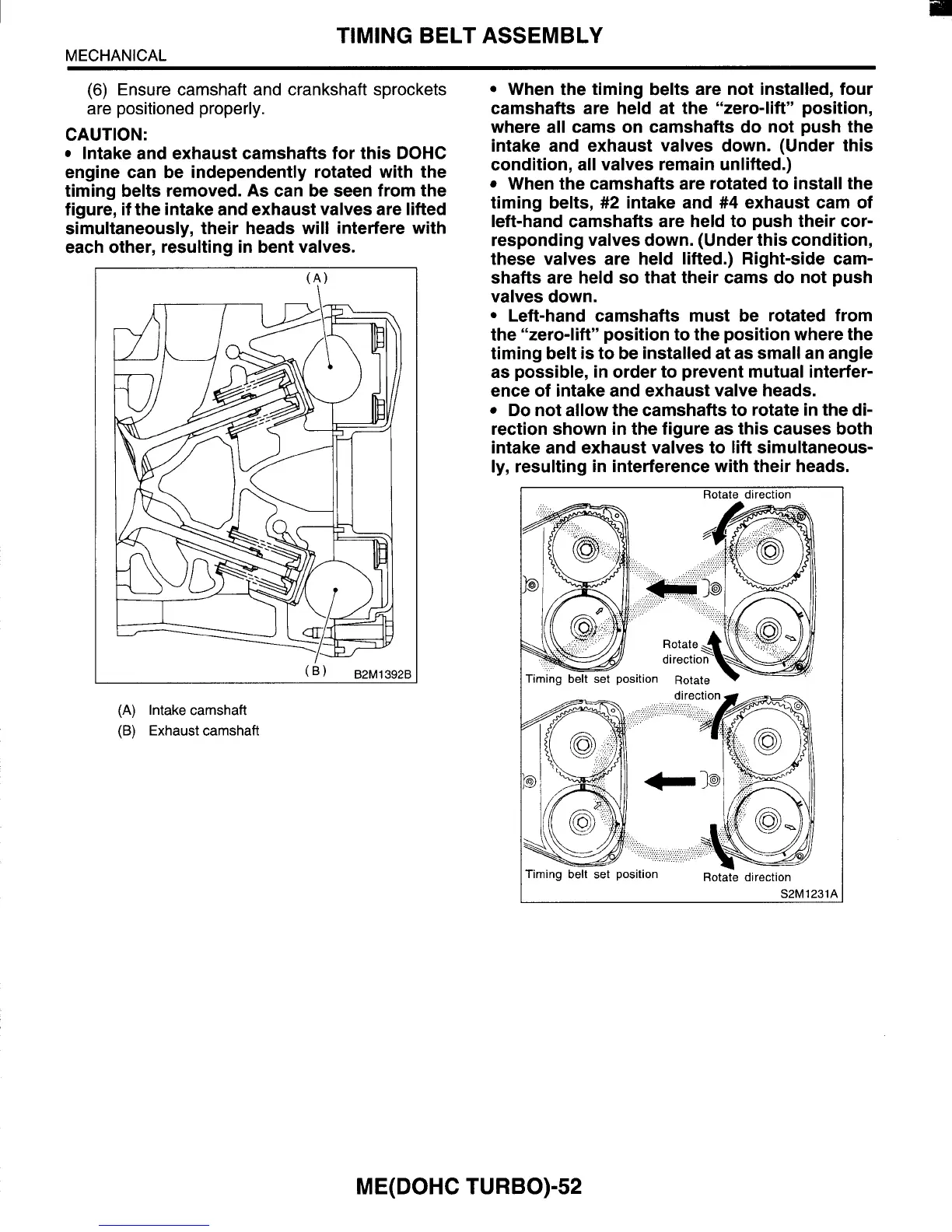
CAUTION:
Intake and exhaust camshafts for this DOHC
engine can be independently rotated with the
timing belts removed. As can be seen from the
figure, if the intake and exhaust valves are lifted
simultaneously, their heads will interfere with
each other, resulting
in
bent valves.
(B)
B2M1392B
(A)
Intake
camshaft
(B)
Exhaust
camshaft
When the timing belts are not installed, four
camshafts are held at the “zero-lift” position,
where all cams on camshafts do not push the
intake and exhaust valves down. (Under this
condition, all valves remain unlifted.)
When the camshafts are rotated to install the
timing belts,
#2
intake and
#4
exhaust cam of
left-hand camshafts are held to push their cor-
responding valves down. (Under this condition,
these valves are held lifted.) Right-side cam-
shafts are held
so
that their cams do not push
valves down.
Left-hand camshafts must be rotated from
the “zero-lift” position to the position where the
timing belt is to be installed at as small an angle
as possible, in order to prevent mutual interfer-
ence of intake and exhaust valve heads.
Do not allow the camshafts to rotate
in
the di-
rection shown
in
the figure as this causes both
intake and exhaust valves to
lift
simultaneous-
ly, resulting in interference with their heads.
I
Rotate
direction
S2M1231A
ME(D0HC TURBO)-52