1110
4. Installation
Common
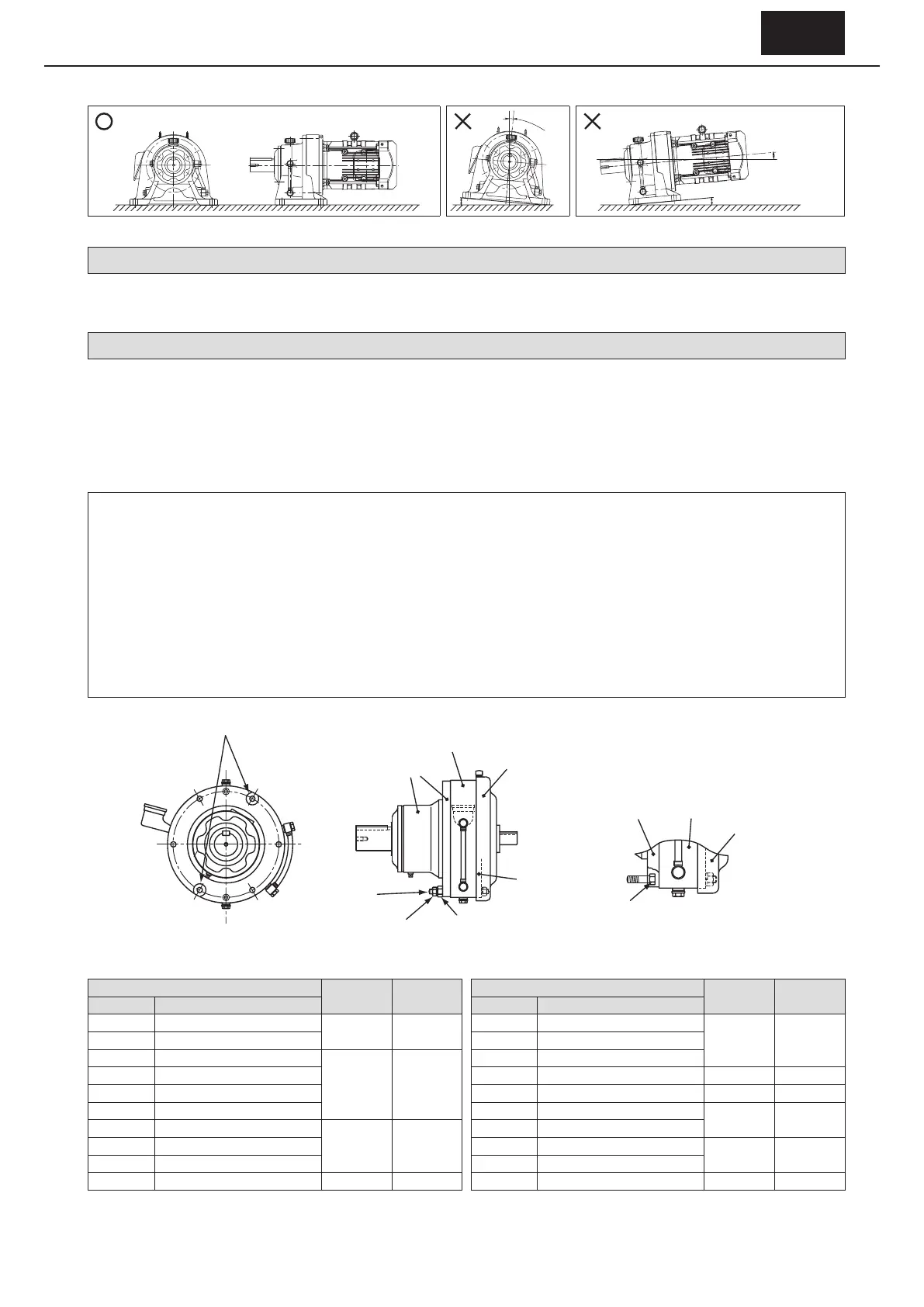
For the horizontal slow speed shaft level type (see P5), attach it as shown in the gure below.
Figure 4-1 Mounting Angle (Example: Foot mount type)
4-3 When Load Condition Is Critical
In cases of extreme vibration or frequent startup, it is recommended to knock the foot unit, and use a mounting bolt of at least class 8.8
(JIS B 1051) strength.
4-4 Flange Type Assembly Issues (Models: CNFM, CHFM, CNF, CHF, etc.)
[1] Remove the fan cover if there is one installed (reducer frame size of 6160 or more).
[2]
Remove the nut and bolt for ring gear housing. Take care when loosening the nut, as the bolt for ring gear housing may rotate together.
[3] A nut of a dierent size to the nut for ring gear housing may be assembled between the nut for ring gear housing and casing when
the device is shipped. Remove this nut, as it is a spacer replacement nut for preventing damage to the faces of the nut for ring gear
housing and casing, as well as for preventing the nut coming free of the threaded section of bolt for ring gear housing.
[4]
Assemble the device to the driven machine, and tighten the nut and bolt for ring gear housing with the tightening torque shown in Table 4.2.
- Disassembly prevention nuts are installed at 2 locations of the bolt for ring gear housing (opposing angles) to prevent disassembly
of the reducer in case the bolt for ring gear housing is removed. Do not remove the disassembly prevention nuts. Removing them
may result in the casing, ring gear housing, internal cover, motor and other parts disassembling and falling o, and may cause injury.
- Using only the disassembly prevention nuts with the nut for ring gear housing removed does not generate a sucient level of
torque. Do not use only the disassembly prevention nuts for ring gear housing for long periods of time, move them excessively or
subject them to shock. Lubricant or grease may leak if there gaps develop between any of the mating faces.
- Tightening the nut for ring gear housing changes the axial force of the disassembly prevention nuts, and may result in them coming
loose. To remove the CYCLO Drive after temporarily assembling the device to the driven machine, check that the disassembly
prevention nuts have not become loose.
Bolts for ring
gear housing
Nuts for ring
Casing
Ring gear housing
Fan cover
Internal cover
Spacer replacement nuts
Internal cove
Casing
Ring gear housing
Disassembly
prevention nuts
Disassembly prevention nuts
(2 locations at opposing angles)
Figure 4-2 Construction Drawings
Table 4-2 Tightening torque for nuts and bolts for ring gear housing
Frame size
Size
Tightening Torque
(N·m)
Frame size
Size
Tightening Torque
(N·m)
Single reduction
Double reduction
Single reduction
Double reduction
606
□
606
□
DA
M6 11
617
□
617
□
DA, 617
□
DB, 617
□
DC
M12 96607
□
607
□
DA 618
□
618
□
DA, 618
□
DB
608
□
-
M8 25
619
□
619
□
DA, 619
□
DB
609
□
609
□
DA 6205 6205DA, 6205DB M16 219
610
□
610
□
DA 6215 6215DA, 6215DB M18 298
611
□
- 6225 6225DA, 6225DB
M20 475
612
□
612
□
DA, 612
□
DB
M10 55
6235 6235DA, 6235DB
613
□
613
□
DA, 613
□
DB, 613
□
DC 6245 6245DA, 6245DB
M24 794
614
□
614
□
DA, 614
□
DB, 614
□
DC 6255 6255DA, 6255DB
616
□
616
□
DA, 616
□
DB, 616
□
DC M12 96
6265
6265DA M30 1590
Note : 1. The symbol
□
in frame size can be "0" or "5."
2. If a nut and bolt are prepared by the customer, a tightening torque that suits the nut and bolt should be used.
3. The position of the disassembly prevention nuts and the shape of each part depend on the frame size.
e