4746
8. Daily Inspection and Maintenance
■
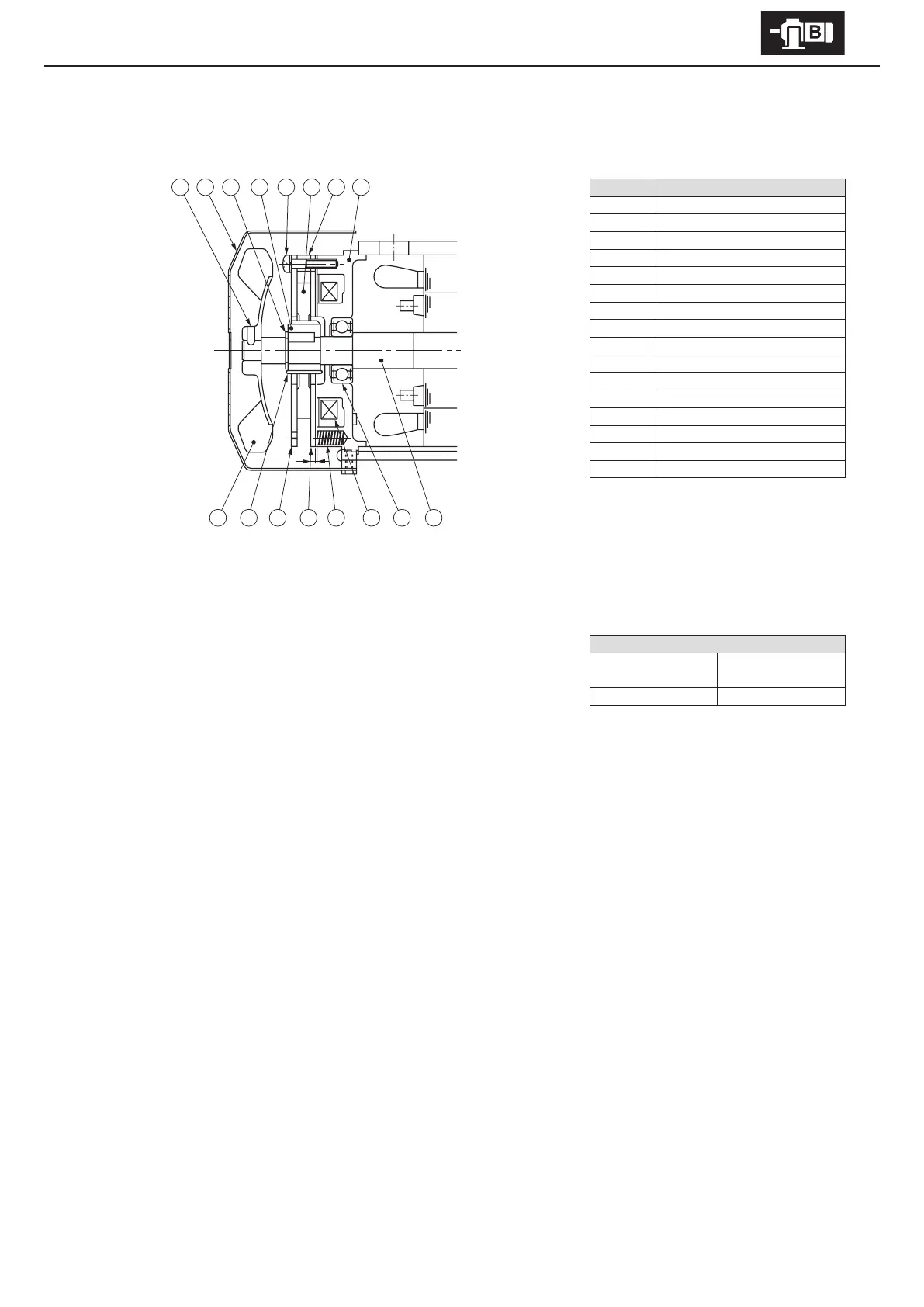
FB-01A1, FB-02A1, FB-05A1 (Indoor Type)
Code Part Name
1 Stationary core
2 Spacer
3 Brake lining
4 Attachment bolt
5 Boss
6 Shaft-retaining C-ring
7 Cover
8 Fan set screw
9 Fan
10 Leaf spring
11 Fixed plate
12 Armature plate
13 Spring
14 Electromagnetic coil
15 Bearing
16 Motor shaft
Note : FB-01A1 does not come with [8][9].
- Gap Inspection
(1) Remove the cover [7].
(2) Insert a gap gauge between the stationary core [1] and the armature plate [12],
and measure the gap. Measure in 3 locations around the circumference.
(3) Adjustment is required if the gap value is near the limit.
- Gap Adjustment
(1) Remove the cover [7].
(2) Loosen the fan set screw [8] and remove the fan [9].
(3) Slightly loosen the attachment bolts [4] and rotate the xed plate [11] counterclockwise, as far as it will go. Then tighten the
attachment bolts [4]. After tightening, measure the gap (G) and check to see if the gap value is between the required value and
the limit. (This operation will reduce the gap by 0.3 mm.)
(4) Turn the power on and o to check brake action.
(5) Attach the fan [9] and cover [7]. Use a fan set screw [8] coated with Three Bond TB2365 (Sumitomo part number EW444WW-01),
and tighten to a torque of 0.3 – 0.5 Nm.
Note : If the the optional brake release bolt is installed, disassemble after removing the release bolt.
Gap value G (mm)
Required value
(original value)
Limit value
0.2 – 0.35 0.5
G
13121110
9
14
15
16
Figure 8-8