2322
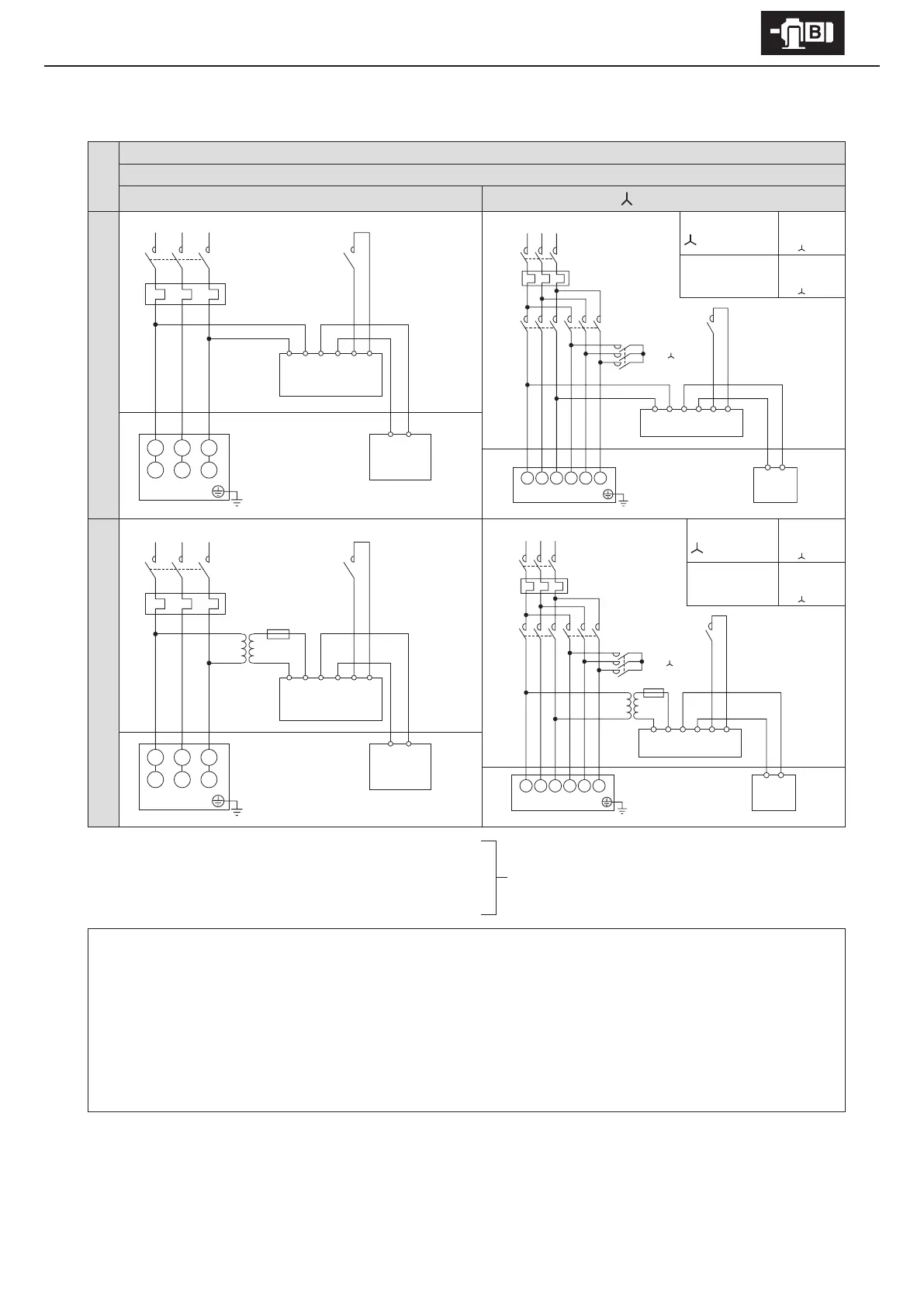
6. Wiring
■
With brake. 3-phase power source. Operates rotating in one direction.
Premium-eciency, 3-phase motor
ESB-250, ESB-250-2
8 lead wires
Direct on-line starting
starting
Quick braking circuit 200V class
At start
Wiring
MC
M
ON
MC
OFF
MC
ON
When acceleration
is completed
wiring
MC
M
ON
MC
ON
MC
OFF
Control Panel Motor
Quick braking circuit 400V class
At start
Wiring
MC
M
ON
MC
OFF
MC
ON
When acceleration
is completed
wiring
MC
M
ON
MC
ON
MC
OFF
Control Panel Motor
MC: Electromagnetic contactor
OLR: Overload protection device or electronic thermal relay
Tr: Transformer capacity 250–600VA, secondary voltage 200–220V
F: Fuse 3–5A
Customer to prepare.
- This diagram shows cases for motors with standard Japanese domestic specications. Please consult with us for motors with
overseas specications.
- For brake types, see Table 1-6 on P7.
- Use with a quick braking circuit. For information on electromagnetic contactors for quick braking circuits, see Table 6-4 on P32.
- For quick braking circuits, gang the brake circuit’s electromagnetic contactor to the motor’s electromagnetic contactor.
- Rectiers are external to the main unit. Rectiers are made for indoor use. Install in an area where they will not come into contact
with water, etc.
- The brake unit is for 200V class. For 400V class power sources, prepare a 400V/200V transformer.
U1 V1 W1
V2 W2 U2
RST
123456
43
Rectier
Brake
MC MC
OLR
Tr
F
400V 200V
Motor
Tr
F
400V 200V
MC
M
MC
Δ
MC
R
OLR
U1
S
V1
T
W1 V2 W2 U2
123456
43
Motor
Rectier
Brake
MC
U1 V1 W1
V2 W2 U2
123456
43
Rectier
Brake
MC MC
OLR
Motor
MC
M
MC
Δ
MC
OLR
U1
V1
W1 V2 W2 U2
123456
43
Motor
Rectier
Brake
MC
Control Panel Motor Control Panel Motor