22
6. Wiring
■
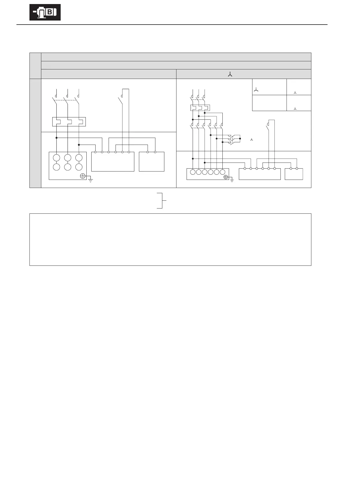
With brake. 3-phase power source. Operates rotating in one direction.
Premium-eciency, 3-phase motor
FB-20, FB-30
8 lead wires
Direct on-line starting
starting
Quick braking circuit
At start
Wiring
MC
M
ON
MC
OFF
MC
ON
When acceleration
is completed
wiring
MC
M
ON
MC
ON
MC
OFF
Control Panel Motor
MC: Electromagnetic contactor
OLR: Overload protection device or electronic thermal relay
Customer to prepare.
- This diagram shows cases for motors with standard Japanese domestic specications. Please consult with us for motors with
overseas specications.
- For brake types, see Table 1-6 on P7.
- Use with a quick braking circuit. For information on electromagnetic contactors for quick braking circuits, see Table 6-4 on P32.
- For quick braking circuits, gang the brake circuit’s electromagnetic contactor to the motor’s electromagnetic contactor.
- Shipped with a short circuit plate connecting rectier terminals 5 and 6. Remove the short circuit plate when wiring.
U1 V1 W1
V2 W2 U2
123456 MN
Rectier Brake
MC MC
OLR
Motor
MC
M
MC
Δ
MC
OLR
U1
V1
W1 V2 W2 U2
1 23456 MN
Motor
Rectier
Brake
MC
MotorControl Panel