18
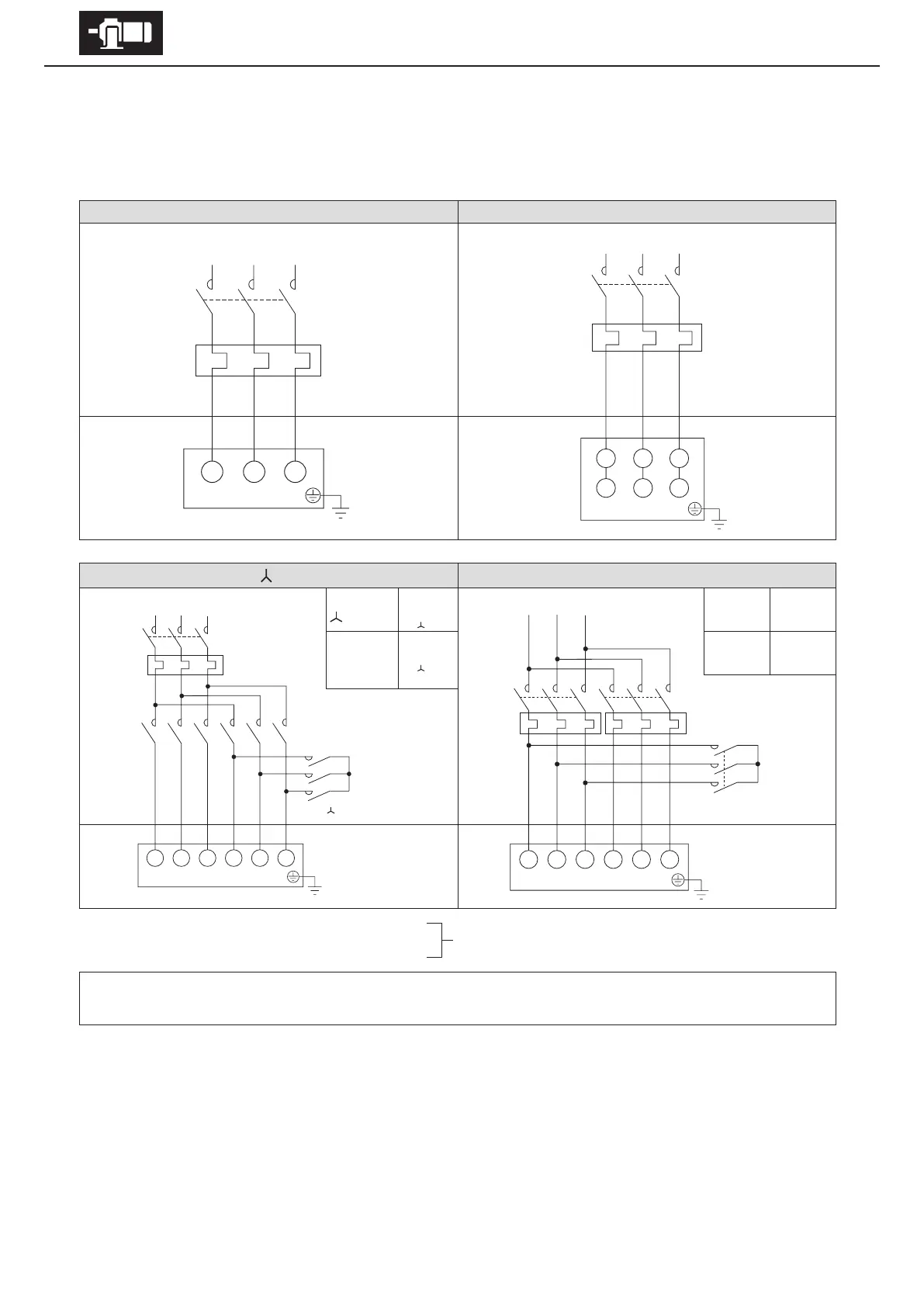
6. Wiring
Shows motor wiring and standard specication for terminals and lead wires that are indicated by symbols.
■
Without brake. 3-phase power source
3-phase motor
Premium-eciency, 3-phase motor
High-eciency, 3-phase motor
3 lead wires 6 lead wires (direct on-line starting)
Control Panel
Control Panel
Motor
Motor
6 lead wires (
starting) 4/8P two speed, single wound rotor (constant torque)
At start
Wiring
MC
M
ON
MC
OFF
MC
ON
When
acceleration
is completed
wiring
MC
M
ON
MC
ON
MC
OFF
When at low
speed
(8P)
MC
L
ON
MC
H1
OFF
MC
H2
OFF
When at
high speed
(4P)
MC
L
OFF
MC
H1
ON
MC
H2
ON
Control Panel
Control Panel
Motor
Motor
MC: Electromagnetic contactor
OLR: Overload protection device or electronic thermal relay
Customer to prepare.
- This diagram shows cases for motors with standard Japanese domestic specications. Please consult with us for motors with
overseas specications.
U1 V1 W1
V2 W2 U2
MC
OLR
Motor
U1 V1 W1 V2 W2 U2
MC
M
OLR
MC
Δ
MC
Motor
SRT
1U 1V 1W 2U 2V 2W
MC
L
OLR
L
RST
MC
H1
MC
H2
OLR
H
Motor
U V W
RST
MC
OLR
Motor