84
Application
Product
12. Adjusting Preset Torque
CAUTION
- Increasing the preset torque will cause the torque limiter to function at a torque value that exceeds the initial setpoint.
Damage to the machine may occur.
12-1 Adjusting Preset Torque for the Spring-Loaded Limit Switch Model
Prestet torque is possible to be adjusted in the range of ±25% value which is after factory shipment.
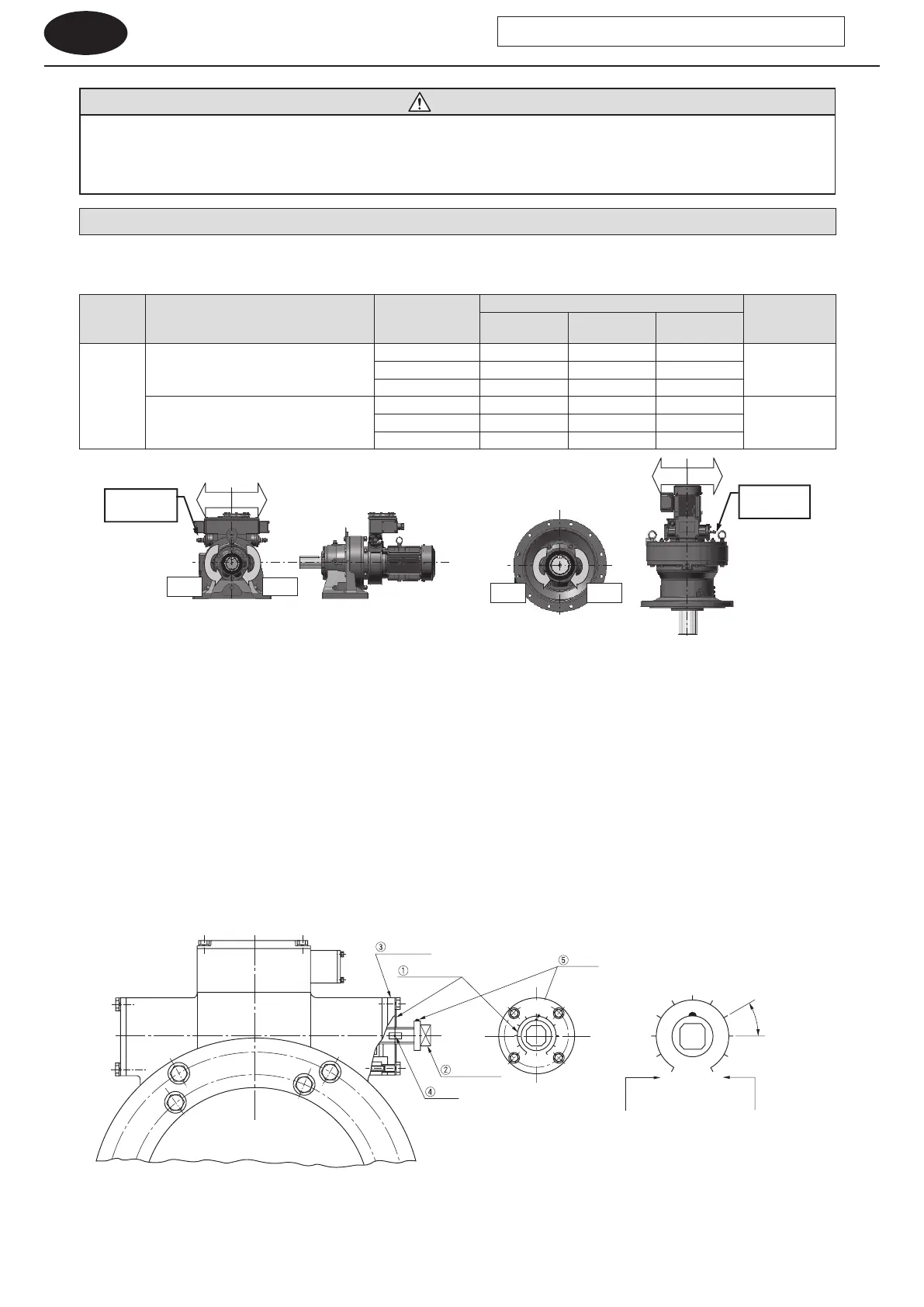
Table 12-1 Propriety to adjust preset torque and position of adjusting bolt
Output
signals
Torque indicator
Rotational
direction of slow
speed shaft
Side of adjustment bolt
Adjustment of
preset torque
1 stage
reduction
2 stage
reduction
3 stage
reduction
1 & 2
Without
Type A (lndicated load ratio: 60 - 100%
or 50 - 100%)
CW Left Right Right
OKCCW Right Left Left
Both Both Both Both
Type B (lndicated load ratio: 0 - 100%)
CW Both Both Both
NGCCW Both Both Both
Both Both Both Both
CCW
CW
Adjustment
bolt
Adjustment
bolt
CCW
CW
RightLeft
RightLeft
- The preset torque is shown at the center of the adjusting scale plate [1] in the gure below.
Torque values indicated by T1 and T2 are positioned at ±150° from the center. Use T1 and T2 as points of reference when changing
the preset torque.
- When it is necessary to increase or decrease the original preset torque, use the adjustment bolt [2].
Adjust torque within a range of ±25% of the preset torque.
Overscaling T1 and T2 is permitted within ±25%. However, do not make adjustment in excess of the maximum preset torque. (See the
selection table in the catalog.)
- An index [4] is stamped in the cut on the side of the threaded section of the adjustment bolt [2]. The index [4] is aligned with the end
face of the case cover [3] when the mark [5] on the adjusting bolt [2] is located at the position of the preset torque on the adjusting
scale plate [1]. Make ne adjustments using this alignment as a base. If the adjustment bolt is too tight or too loose, rst reset the
adjustment bolt to align the index [4] with the end face of the case cover [3]. Then make adjustments.
Mark
Adjustment scale plate
Case cover
Adjustment bolt
(Indicator scale details)
Torque rating
30°
Shows the rated torque
when the adjustment bolt
is turned 150° to the left.
Shows the rated torque
when the adjustment bolt
is turned 150° to the right.
Indicator
N·m
PRESET
T1 T2
N·m
Figure 12-1 Adjusting Preset Torque
Note : 1. For the reversible rotation specication, an adjustment bolt and adjustment scale plate will be located on both sides.
2. In the case of the B-type torque indicator (indicating a load factor of 0 – 100%), it is not possible to adjust the preset torque.
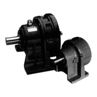
CYCLO Drive with Torque Limiter