82
Application
Product
DANGER
- Do not handle the unit when cables are live. Be sure to turn off the power when performing operations on the unit;
otherwise, electric shock may result.
- Connect a power cable to the unit in accordance with the maintenance manual; otherwise, electric shock or re may result.
- Do not forcibly bend, pull, or clamp the power cable and lead wires; otherwise, electric shock or re may result.
CAUTION
- When wiring, follow the facility's electrical codes and extension regulations to prevent burns, electric shocks, injuries, and
re.
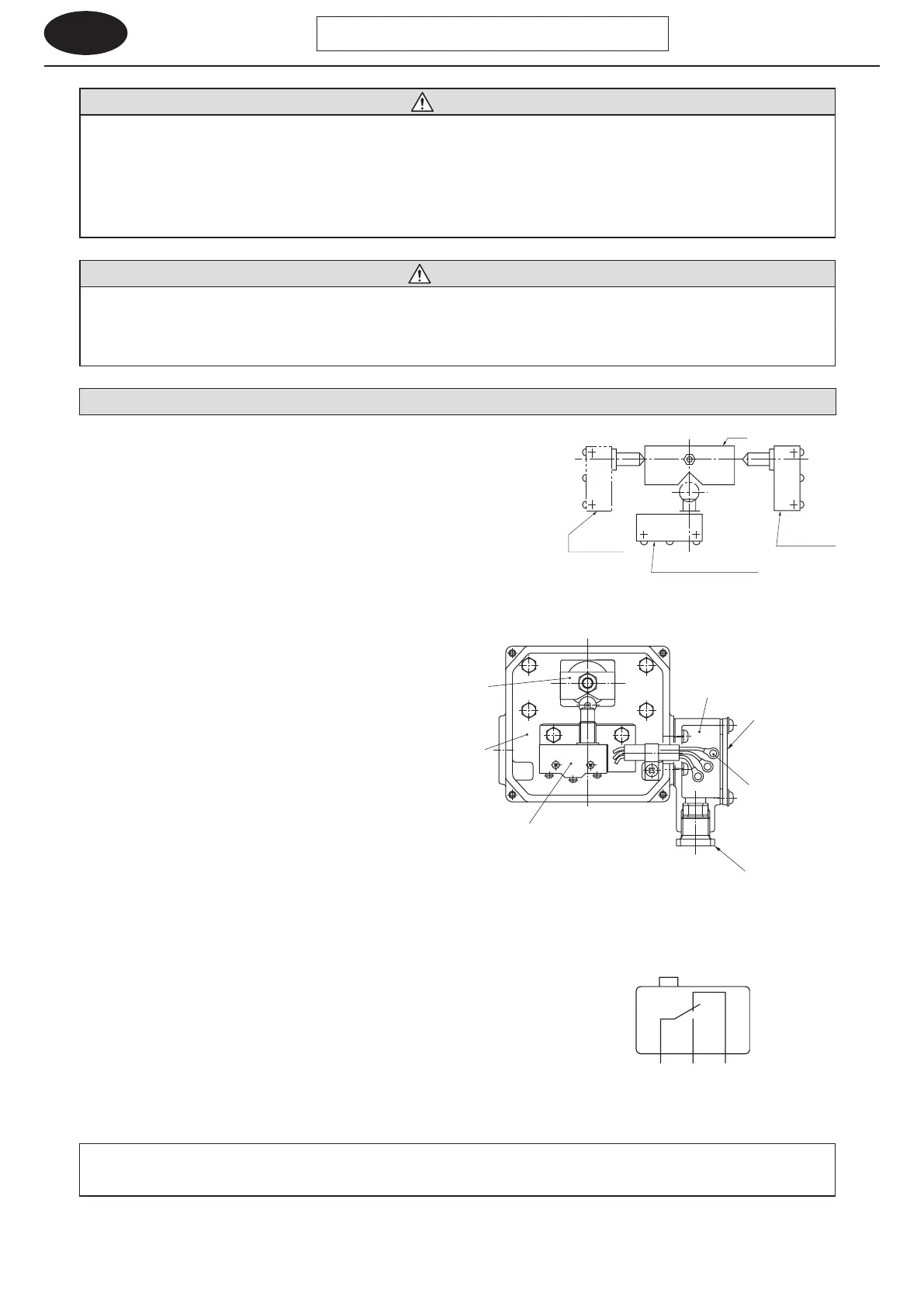
11-1 Wiring for a Spring-Loaded Limit Switch
(1) Limit Switch Type (1-Point Signal, 2-Point Signal, 3-Point Signal)
- When the preset torque is reached, the dog activates the limit switch, which
outputs a signal.
- Depending on manufacturing specications 1
3 point signal output is
available.
(Types that have 1
3 limit switches.)
(2) Limit Switch Wiring
[1] Remove the terminal cover on the terminal box, feed
the cabtyre cable through the cable gland for marine
use and connect it to the limit switch terminals.
[2] Of the three lead wires, connect as follows:
- For contact pointa, terminal symbols C (COMMON) and
NO (NORMALLY OPEN)
- For contact pointb, terminal symbols C (COMMON)
and NC (NORMALLY CLOSED)
[3] Make wiring within the terminal box. The construction
of the terminal box makes wiring be possible.
[4] The limit switch may activate at startup if startup torque
exceeds preset torque (when shock occurs at startup,
the motor is equipped with a brake, etc.). In this case,
install a motor timer to disable the limit switch until the
load torque becomes less than the preset torque.
Note : 1. For 2-point signal systems, there are two terminal boxes; for 3-point signal systems,
there are three terminal boxes.
2. The cable gland for marine use conforms to JISF8801 (for boxes) and 15-b.
11. Wiring
Limit switch for
sub-motor
Limit switch for main motor
(Type Z-15GQ-B)
(Type Z-15GQ-22B)
(Type Z-15GQ-B)
Limit switch for
auxiliary signal
Limit switch
Cable gland for marine use
Limit switch
lead terminals
Terminal box
Terminal cover
Switch box
Dog
Figure 11-1 Limit Switch
Figure 11-3 Type of Contact (1c)
- To prevent moisture from entering the cable port, seal openings with sealant (for example, putty).
- Do not move the position of the limit switch, or the torque limiter does not work properly because preset torque was changed.
CYCLO Drive with Torque Limiter
Figure 11-2 Terminal Box·Switch Box