3736
8. Daily Inspection and Maintenance
Common
8-2 Conrmation of Lubrication Method
Please look for the relevant items and make certain to do maintenance. Neglecting maintenance is a source of trouble.
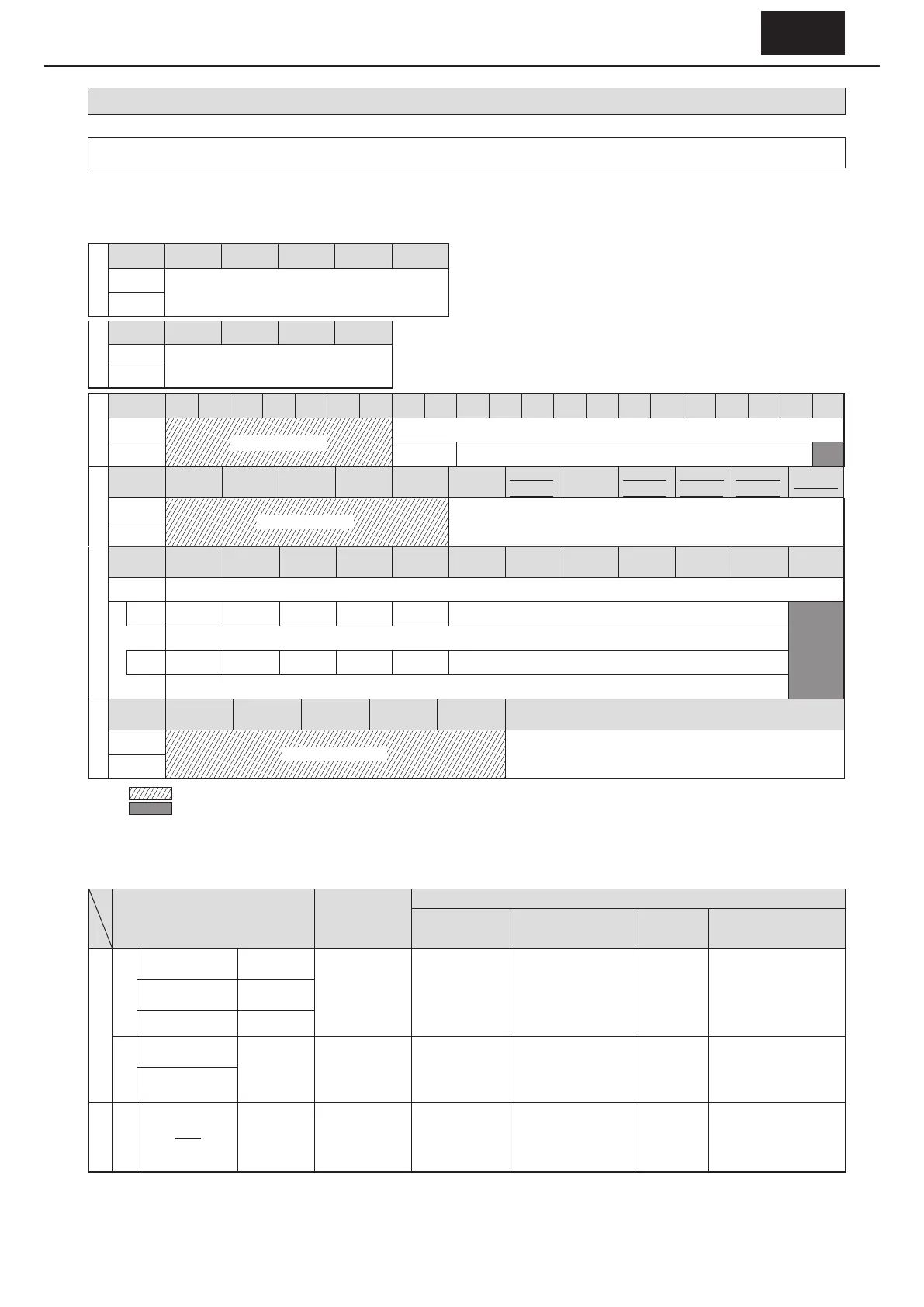
- Check Table 8-2 for the lubrication method employed by the gear unit of the model used.
- Table 8-3 lists pages that can be referenced regarding lubrication maintenance.
Table 8-2 Standard Lubrication Methods for Gear Units by Type (When driven at standard input speed)
SK series
Frame size
607
□
SK 608
□
SK 609
□
SK 610
□
SK 611
□
SK
Horizontal
Long-life grease
Vertical
Low reduction
ratio series
Frame size
613
□
614
□
616
□
617
□
Horizontal
Oil Bath
Vertical
Single Reduction
Frame size
606
□
607
□
608
□
609
□
610
□
611
□
612
□
613
□
614
□
616
□
617
□
618
□
619
□
6205 6215 6225 6235 6245 6255 6265 6275
Horizontal
Long-life grease
Oil Bath
Vertical Oil Bath Plunger pump (force-feed lubrication)
Frame
size
606
□
DA 607
□
DA 609
□
DA 610
□
DA
612
□
DA
612
□
DB
613
□
DA
613□DB
613□DC
614
□
DA
614□DB
614□DC
616□DA
616□DB
617□DA
617□DB
618□DA
Horizontal
Long-life grease
Grease
Vertical
Double Reduction
Frame
size
616
□
DC 617
□
DC 618
□
DB
619
□
DA
619
□
DB
6205DA
6205DB
6215DA
6215DB
6225DA
6225DB
6235DA
6235DB
6245DA
6245DB
6255DA
6255DB
6265DA 6275DA
Horizontal
Oil Bath
Vertical
Reduction
ratio
– 473 – 841 – 1015 – 2065 – 1849 – 2537
Plunger pump (force-feed lubrication)
Reduction
ratio
493 – 1003 – 1247 – 2537 – 2065 – 3045 –
Grease
Triple Reduction
Frame
size
606
□
TA 607
□
TA 609
□
TA 610
□
TA
612
□
TA
612
□
TB
Frame sizes not listed to the left
Horizontal
Long-life grease
Grease
Vertical
Note : 1. Indicates universal mounting direction.
2.
Indicates independent lubrication using a trochoid pump. See “6-7 Wiring for Motorized Trochoid Pump Motor” (P33)
3. The symbol
□
in frame size can be "0", "5” or "H".
4. For underlined frame sizes, the horizontal chain ight sludge collector specication is set to oil lubrication.
5. If input speed is not standard, consult with us.
Table 8-3 Maintenance Manual Pages that can be Referenced Regarding Lubrication Maintenance
Lubrication method
Oiling, greasing at
time of purchase,
prior to operation
Location of information on maintenance technique
Oil, grease
change, replenish
intervals
Recommended lubricating
oil,
grease
Oil ll quantity
Grease supply
quantity
Oil ll and drain procedures
Grease supply and discharge
procedures
Gear unit
Oil lubrication
Oil Bath Self-lubricating
Required
8−3
(1)
P38
8−3
(2)
P38
8−3
(3)
P39
8−3
(4), (5)
P39, 40
Plunger
system
force-feed
lubrication
Trochoid
system
Independent
lubrication
Grease lubrication
Long-life grease
Self-lubricating Not required
8-4
(1)
P41
8-4
(2)
P41
8-4
(3)
P42
8-4
(4)
P43
Other than long-life
grease
Motor bearing unit
Grease lubrication
Self-lubricating Not required
8-6
(1)
P44
8-6
(2)
P45
8-6
(1)
P44
8-6
(3)
P45
Note : For plunger pump type (force-feed lubrication) models, in the case that the slow speed shaft does not rotate continuously (example: the slow speed
shaft only rotates 90° or less), consult with us. As Figure 10-2 on P74 shows, plunger pump [40] is driven by cam [47] on the slow speed shaft unit. If the
machine is not driven at a continuous, standard input speed, consideration must be made for providing sucient lubrication to the reducer.