2524
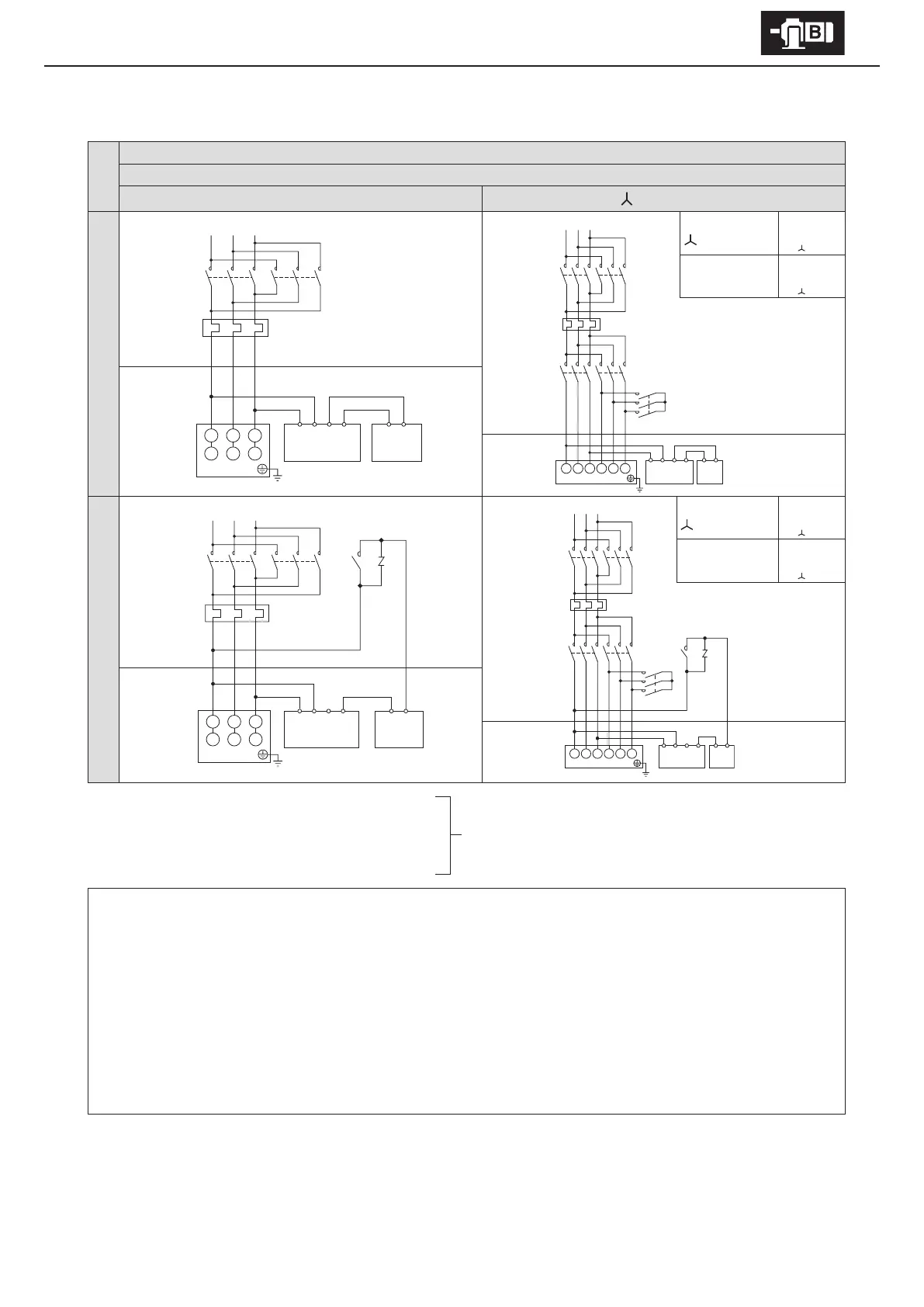
6. Wiring
■
With Brake. 3-phase motor. Plugging operation
Premium-eciency, 3-phase motor
FB-8E – FB-15E
8 lead wires
Direct on-line starting
starting
Normal braking circuit
At start
Wiring
MC
M
ON
MC
OFF
MC
ON
When acceleration
is completed
wiring
MC
M
ON
MC
ON
MC
OFF
Control Panel Motor
Quick braking circuit
At start
Wiring
MC
M
ON
MC
OFF
MC
ON
When acceleration is
completed
wiring
MC
M
ON
MC
ON
MC
OFF
Control Panel Motor
Electromagnetic contactor for normal and reverse rotation
MC: Electromagnetic contactor
OLR: Overload protection device or electronic thermal relay
VR: Varistor (for protecting contact points, rectier, etc.)
Customer to prepare.
- This diagram shows cases for motors with standard Japanese domestic specications. Please consult with us for motors with
overseas specications.
- For brake types, see Table 1-6 on P7.
- Brake action delay time is dierent for normal and quick braking circuits.
Table 7-2 on P35 shows action delay time. Choose the circuit that matches work requirements.
- Use a quick braking circuit to improve hoisting equipment and stopping precision.
- Use a quick braking circuit when a phase-advancing capacitor is mounted.
- For information on electromagnetic contactors and varistors for quick braking circuits, see Table 6-4 on P32.
- For plugging operations using a quick braking circuit, gang the brake circuit’s electromagnetic contactors to the motor’s normal
and reverse rotation electromagnetic contactors.
RS
RS
T
OLR
U1 V1 W1
V2 W2 U2
1234 MN
Rectier Brake
Motor
MC
M
MC
Y
MC
Δ
OLR
U1 V1 W1 V2 W2 U2
1234 MN
Motor
Rectier Brake
T
OLR
VR
MC
U1 V1 W1
V2 W2 U2
Motor
1234 MN
Rectier Brake
MC
M
MC
Y
RST
MC
Δ
OLR
U1 V1 W1 V2 W2 U2
Motor
VR
MC
1234
Rectier
Brake
Reverse rotation
Normal rotation
Reverse rotation
Normal rotation
Reverse rotation
Normal rotation
Reverse rotation
Control Panel Motor Control Panel Motor