26
6. Wiring
■
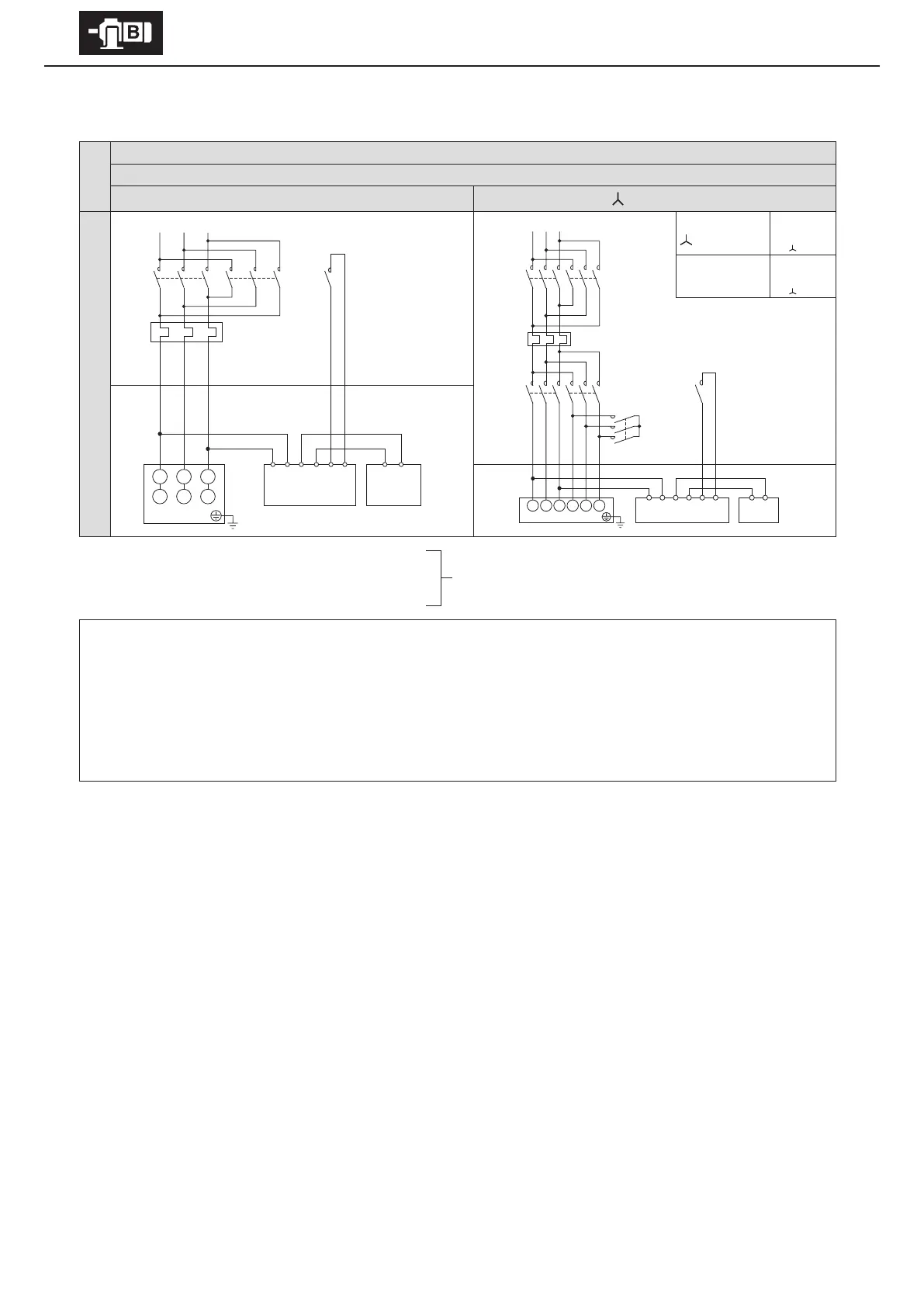
With Brake. 3-phase motor. Plugging operation
Premium-eciency, 3-phase motor
FB-20, FB-30
8 lead wires
Direct on-line starting
starting
Quick braking circuit
At start
Wiring
MC
M
ON
MC
OFF
MC
ON
When acceleration
is completed
wiring
MC
M
ON
MC
ON
MC
OFF
Control Panel Motor
Electromagnetic contactor for normal and reverse rotation
MC: Electromagnetic contactor
OLR: Overload protection device or electronic thermal relay
Customer to prepare.
- This diagram shows cases for motors with standard Japanese domestic specications. Please consult with us for motors with
overseas specications.
- For brake types, see Table 1-6 on P7.
- Use with a quick braking circuit. For information on electromagnetic contactors for quick braking circuits, see Table 6-4 on P32.
- Shipped with a short circuit plate connecting rectier terminals 5 and 6. Remove the short circuit plate when wiring.
- For plugging operations, gang the brake circuit’s electromagnetic contactors to the motor’s normal and reverse rotation
electromagnetic contactors
OLR
MC
U1 V1 W1
V2 W2 U2
123456MN
Rectier Brake
Motor
MC
M
MC
Y
MC
Δ
OLR
MC
U1 V1 W1 V2 W2 U2
123456 MN
Motor
Rectier
Brake
Reverse rotation
Normal rotation
Reverse rotation
Control Panel Motor