3534
7. Operation
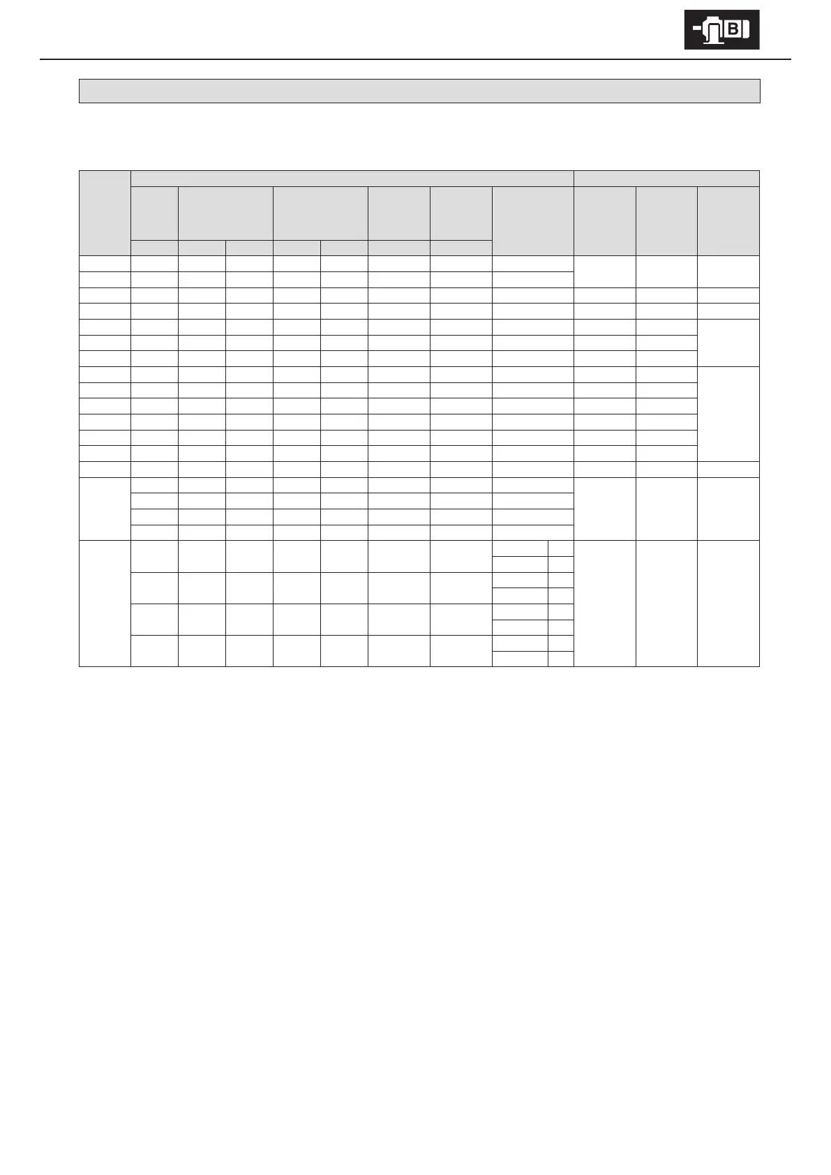
7-3 Brake Torque and Activation Delay Time
The table below shows standard specication brake types, their brake torque, and their relationship to brake activation delay time.
Table 7-2 Brake Torque and Activation Delay Time
Brake
type
Motor capacity (kW) Brake Activation Delay Time (s)
3-phase
motor
Premium
eciency,
3-phase motor
AF motor for
inverter
Premium-
eciency,
3-phase motor
for inverter
HIgh-
eciency,
3-phase
motor
Brake torque
(Dynamic friction
torque) (N
・
m)
Normal braking
circuit
(Simultaneous
turn-o circuit)
Normal braking
circuit for
inverter
(Simultaneous
turn-o circuit)
Quick
braking
circuit
4P 4P 6P 4P 6P 4P 4P
FB-01A1 0.1
- - - - - -
1.0
0.15 – 0.2 0.08 – 0.12 0.015 – 0.02
FB-02A1 0.2 0.25
- -
0.1
- - -
2.0
FB-05A1 0.4
- -
0.2
- -
0.2 4.0 0.1 – 0.15 0.03 – 0.07 0.01 – 0.015
FB-1D 0.55
- -
0.4
- -
0.4 7.5 0.2 – 0.3 0.1 – 0.15 0.01 – 0.02
FB-1E
-
0.75
- - -
0.75
-
7.5 0.25 – 0.45 0.15 – 0.25
0.01 – 0.03FB-1HE
-
1.1
- - - - -
11 0.45 – 0.65 0.25 – 0.35
FB-2E
-
1.5
- - -
1.5
-
15 0.35 – 0.55 0.15 – 0.25
FB-3E
-
2.2
- - -
2.2
-
22 0.75 – 0.95 0.4 – 0.5
0.02 – 0.04
FB-4E
-
3.0
- - - - -
30 0.65 – 0.85 0.3 – 0.4
FB-5E
-
3.7
- - -
3.7
-
40 1.1 – 1.3 0.4 – 0.5
FB-8E
-
5.5
- - -
5.5
-
55 1.0 – 1.2 0.3 – 0.4
FB-10E
-
7.5
- - -
7.5
-
80 1.8 – 2.0 0.6 – 0.7
FB-15E
-
11
- - -
11
-
110 1.6 – 1.8 0.5 – 0.6
FB-20
-
15
- - -
15
-
150
- -
0.06 – 0.14
FB-30
- -
15
- - - -
220
- -
0.03 – 0.11
-
18.5 18.5
- -
18.5
-
190
-
22 22
- -
22
-
220
-
30
- - -
30
-
200
ESB-250
(Horizontal)
ESB-250-2
(Vertical)
- - -
30 18.5
- -
Horizontal 212
- -
0.065
Vertical 195
-
37
-
37 22 37
-
Horizontal 266
Vertical 244
-
45 30
-
30 45
-
Horizontal 320
Vertical 292
- -
37
- - - -
Horizontal 372
Vertical 390
Note : 1. Brake type may dier depending on specication. Check the nameplate.
2. Brake torque will change according to operating environment, operating conditions, the condition of the friction surface, etc. In
particular, brake torque may not be at the prescribed level for initial operation, and after a long period of inactivity. In such a case
turn the brake on and o under as light load as possible to contact the brake’s friction surfaces.
3. Brake activation delay time will change according to the brake’s wiring circuit. Select the optimum circuit for the application.