5958
8. Daily Inspection and Maintenance
■
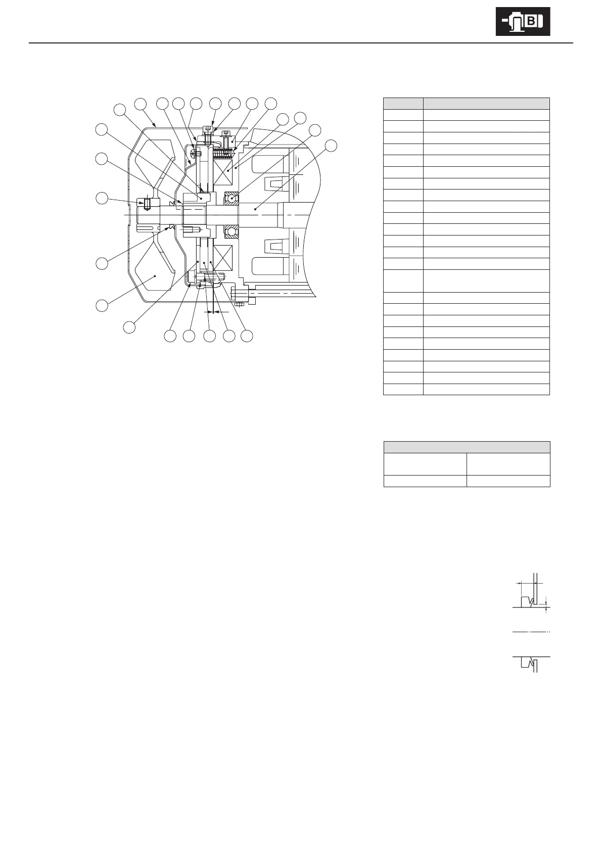
FB-1D (Outdoor Type)
Code Part Name
1 Armature plate
2 Brake lining
3 Spacer
4 Gap adjusting shims
5 Attachment bolt
6 Fixed plate
7 Fan
8 V-ring
9 Fan set screw
10 Shaft retaining C-ring
11 Boss
12 Leaf spring
13 Cover
14 Waterproof cover
15
Waterproof cover attachment
bolts
16 Waterproof seal
17 Brake release bolt
18 Manual release protection spacer
19 Brake release
20 Spring
21 Electromagnetic coil
22 Stationary core
23 Bearing
24 Motor shaft
6
7
8
9
10
11
12
21
22
23
24
G
- Gap Inspection
(1) Remove the brake release bolt [17] and the manual release prevention spacer [18].
(2) Remove the cover [13].
(3) Loosen the fan set screw [9] and remove the fan [7].
(4) Remove the brake release [19]. (2 Places)
(5) Remove the waterproof seal [16].
(6) Insert a gap gauge between the stationary core [22] and the armature plate [1],
and measure the gap. Measure in 3 locations around the circumference.
(7) Adjustment is required if the gap value is near the limit.
(Gap adjustment shim thickness is approximately 0.2 – 0.25 mm. Adjustment
cannot be made at a lower value.)
- Gap Adjustment
(1) Remove the brake release bolt [17] and the manual release prevention spacer [18].
(2) Remove the cover [13].
(3) Loosen the fan set screw [9] and remove the fan [7].
(4) Pull o the V-ring [8].
(5) Remove the brake release [19]. (2 Places)
(6) Remove the waterproof seal [16].
(7) Remove the waterproof cover attachment bolts [15], and remove the waterproof cover [14].
(8) Loosen the attachment bolts [5] and remove the spacers [3], gap adjusting shims [4], attachment bolts [5], xed
plate[6] as a set. When removing the attachment bolts [5] make certain not to omit the gap adjustment shims [4].
(9) The gap adjusting shims [4] have a thickness of 0.2 – 0.25 mm. Reduce the number of shims according to the
wear conditions, then reassemble the spacers [3], gap adjustment shims [4], attachment bolts [5] and the xed
plate [6] as a set.
(10) Check the gap G, and readjust the shims if there is a large dierence between it and the required value.
(11) Attach the waterproof cover [14] using the attachment bolts [15]. Attach the waterproof cover [14] so that the
gap (A) between its hole and the motor shaft [24] is nearly uniform.
(12) Clean the surface of the waterproof seal [16] to remove impurities.
(13) As shown in the construction diagram, install the waterproof seal [16] between the stationary core [22] and the waterproof
cover [14]. Then attach the brake release [19]. Insert the waterproof seal [16] with its arrow mark pointing toward the load side.
Align the hole in the waterproof seal [16] for the release bolt with the position of release bolt [17]. Attach the waterproof seal [16]
so that its protrusion ts snuggly around the entire circumference of the groove for the stationary core [22]. Otherwise water
could leak in.
(14) Turn the power on and o to check brake action.
(15) Attach the V-ring [8]. Wipe o the lip and surface near the lip of V-ring [8], lightly coat the the lip contact surface with grease,
and attach. Observe the attaching dimension (B
=
4.5mm).
(16) Attach the fan [7] and cover [13]. Use a fan set screw [9] coated with Three Bond TB2365 (Sumitomo part number EW445WW-01),
and tighten to a torque of 0.85 – 1.05 Nm. Finally, attach the brake release bolt [17] and the manual release prevention spacer
[18].
Gap value G (mm)
Required value
(original value)
Limit value
0.3 – 0.4 0.6
B
A
Figure 8-23