86
Application
Product
14. Torque Indicator
14-1 Torque Indicator
(1) Checking the Torque Indicator
- The torque indicator is zero adjusted, and the preset torque is adjusted before shipment.
After the reducer has been connected to equipment, if zero is not indicated when the reducer is at rest, it is possible that a small load
is already being applied to the output shaft. Do not readjust the zero point.
- The relationship between the direction of pointer deection and slow speed shaft rotation (seen from the slow speed shaft side) is
shown below.
Single reduction type: pointer opposite direction of the slow speed shaft
Double, triple reduction types: pointer in the same direction as the slow speed shaft
- The indicator scale displays the load factor, with 100% being the preset torque. Accuracy is within 10% of the overall load range.
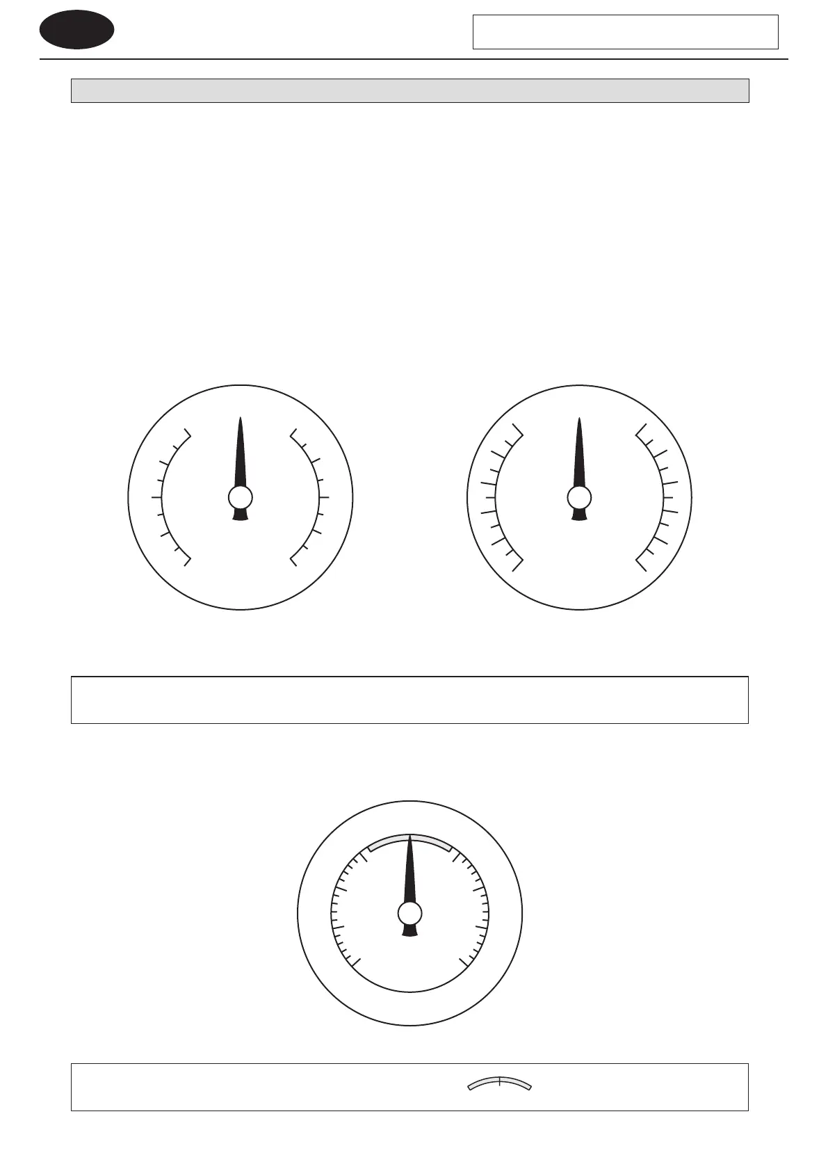
(2) A-Type Torque Indicator
The A-type torque indicator displays load factors of 60 – 100% (depending on the combination of preset torque and reduction ratio
50 – 100%).
60 60
70 70
80 80
90 90
100 100
%
%
50
100 100
50
60 60
90
70 70
80 80
90
Figure 14-1 A-Type Torque Indicator
(60 – 100% load factor display)
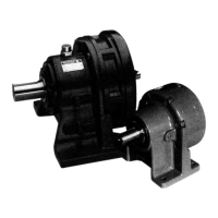
Figure 14-3 B-Type Torque Indicator (0 – 100% load factor display)
Figure 14-2 A-Type Torque Indicator
(50 – 100% load factor display)
- The pointer may deect slightly when stopped or under no load. This is not a problem.
- For the reversible rotation specication, when left and right preset torques dier, the pointer position will be slightly oset.
(3) B-Type Torque Indicator
The B-type torque indicator displays load factors of 0 – 100%.
- In the case of a B-type torque indicator, the pointer will stop in the range of when load is removed.
- Preset torque cannot be changed. Do not turn the adjustment bolt.
%
0
25 25
50 50
75 75
100 100
CYCLO Drive with Torque Limiter