66
8. Daily Inspection and Maintenance
■
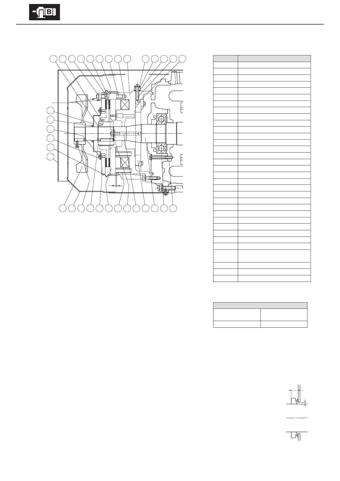
FB-30 (Outdoor Type)
- Gap Inspection
(1) Remove the outdoor cover [33] and the cover [16].
(2) Loosen the fan set screw [17] and remove the fan [15].
(3) Remove the waterproof seal [32].
(4) Insert a gap gauge between the stationary core [6] and the armature plate [20],
and measure the gap. Measure in 3 locations around the circumference.
(5) Adjustment is required if the gap value is near the limit.
- Gap Adjustment
(1) Remove the outdoor cover [33] and the cover [16].
(2) Loosen the fan set screw [17] and remove the fan [15].
(3) Pull o the V-ring [29].
(4) Remove the waterproof seal [32].
(5) Insert a gap gauge between the stationary core [6] and the armature plate [20] and rotate to the right the gap adjusting nuts [12]
that are attached to ends of the stud bolts [8]. If large adjustments to the gap are not possible, decrease the number of adjusting
washers [10]. There are 3 gap adjusting nuts [12]. Adjust these in turn so that 3 positions on the circumference are uniformly at
the required gap.
(6) Turn the power on and o to check brake action.
(7) Attach the waterproof cover [28] so that the gap (A) between its hole and the motor shaft [27] is nearly uniform.
(Only when the waterproof cover [28] has been removed)
(8) Clean the surface of the waterproof seal [32] to remove impurities.
(9) As shown in the construction diagram, install the waterproof seal [32] between the stationary core [6] and the
xed plate [19]. (Be careful that the waterproof seal [32] does not meander. Otherwise water could leak in.)
(10) Attach the V-ring [29]. Wipe o the lip and surface near the lip of V-ring [29], lightly coat the the lip contact
surface with grease, and attach. Observe the attaching dimension (B
=
7mm).
(11) Thoroughly coat the gap (C) between the gap adjusting nuts [12], the stud bolts [8] and the xed plate [19] with
waterproof adhesive (Three Bond 1102).
(12) Attach the fan [15], cover [16] and outdoor cover [33].
Code Part Name
1 Roller
2 Brake release bolt
3 Rubber packing
4 Manual release prevention spacer
5 Seal washer
6 Stationary core
7 Electromagnetic coil
8 Stud bolt
9 Brake lining
10 Adjusting washer
11 Spring washer
12 Gap adjusting nut
13 Boss
14 Shaft-retaining C-ring
15 Fan
16 Cover
17 Fan set screw
18 Leaf spring
19 Fixed plate
20 Armature plate
21 Spring
22 Nut
23 Tap-end stud
24 Ball bearings
25 Release lever
26 Bearing cover
27 Motor shaft
28 Waterproof cover
29 V-ring
30
Waterproof cover attachment
bolts
31 Waterproof cover gasket
32 Waterproof seal
33 Outdoor cover
Note : The shape of the outdoor cover [33] diers
for vertical type specication.
Gap value G (mm)
Required value
(original value)
Limit value
0.6 – 0.7 1.5
B
A
12345
28
32
29
30
31
33
67891011121314
15 18 19 20 21 22 2316 17 25 27 24 26
G
C
Figure 8-30