48
8. Daily Inspection and Maintenance
■
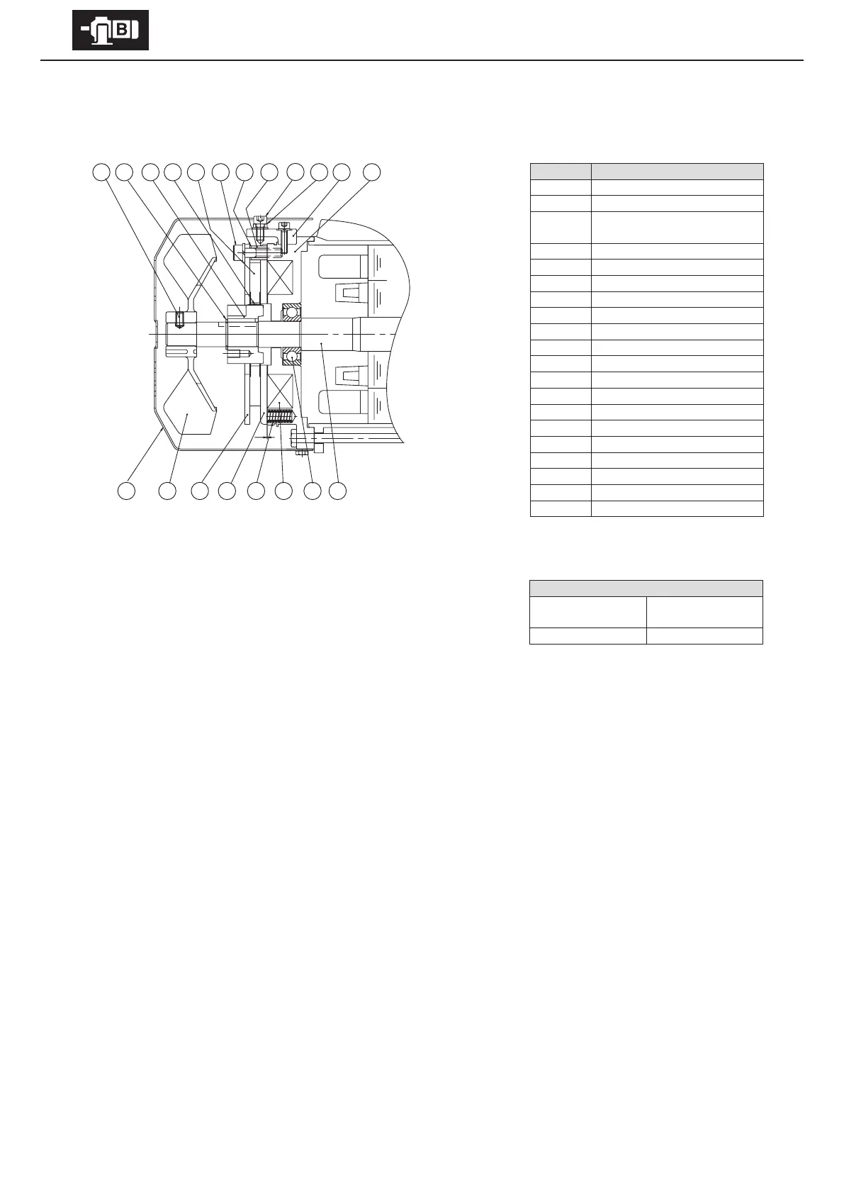
FB-1D (Indoor Type)
Code Part Name
1 Stationary core
2 Brake release
3
Manual release protection
spacer
4 Brake release bolt
5 Spacer
6 Gap adjusting shims
7 Attachment bolt
8 Brake lining
9 Leaf spring
10 Boss
11 Shaft-retaining C-ring
12 Fan set screw
13 Cover
14 Fan
15 Fixed plate
16 Armature plate
17 Spring
18 Electromagnetic coil
19 Bearing
20 Motor shaft
- Gap Inspection
(1) Remove the brake release bolt [4] and the manual release prevention spacer [3].
(2) Remove the cover [13].
(3) Insert a gap gauge between the stationary core [1] and the armature plate [16]
and measure the gap. Measure in 3 locations around the circumference.
(4) Adjustment is required if the gap value is near the limit.
(Gap adjustment shim thickness is approximately 0.2 – 0.25 mm. Adjustment cannot be made at a lower value.)
- Gap Adjustment
(1) Remove the brake release bolt [4] and the manual release prevention spacer [3].
(2) Remove the cover [13].
(3) Remove the fan set screw [12] and remove the fan [14].
(4) Loosen the attachment bolts [7] and remove the spacers [5], gap adjustment shims [6], attachment bolts [7] and xed plate [15]
as a set. When removing the attachment bolts [7] make certain not to omit the gap adjustment shims [6].
(5) The gap adjustment shims [6] have a thickness of 0.2 – 0.25 mm. Reduce the number of shims according to the wear
conditions, then reassemble the spacers [5], gap adjustment shims [6], attachment bolts [7] and the xed plate [15] as a set.
(6) Check the gap G, and readjust the shims if there is a large dierence between the gap and the required value.
(7) Turn the power on and o to check brake action.
(8) Attach the fan [14], fan set screw [12] and cover [13]. Use a fan set screw [12] coated with Three Bond TB2365 (Sumitomo part
number EW445WW-01), and tighten to a torque of 0.85 – 1.05 N·m. Finally, attach the brake release bolt [4] and the manual
release prevention spacer [3].
Gap value G (mm)
Required value
(original value)
Limit value
0.3 – 0.4 0.6
3
11
4
10
9
7
8
13 14 15 16 17 18 19
20
12
5
6
1
2
G
Figure 8-9