E-18 Sun Fire X4100/X4100 M2 and X4200/X4200 M2 Servers Service Manual • August 2009
E.13 Fan Module Connector
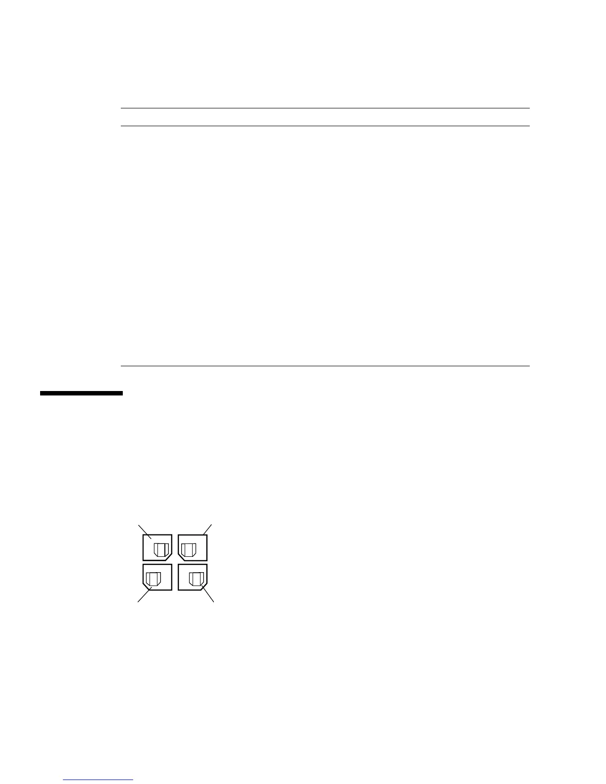
The fan module connectors and their corresponding descriptions are shown in the
figure and table in this section.
FIGURE E-13 Fan Module Connector
B6 -PS_ON Enable for main supply output
C1 Return Ground
C2 Tach _1 Fan tach output (2 pulses per rev)
C3 Return Ground
C4 +3.3V SB +3.3 V Standby Output
C5 SCL EEPROM Serial Clock Input
C6 VIN_GOOD Input voltage above minimum spec
D1 -PS_Present Present–active low (PU)
D2 NC No Connect (Tach_2 if two-fan design)
D3 Return Ground
D4 +3.3V SB +3.3 V Standby Output
D5 S_INT(Alert) Intrusion switch alert
D6 POK Output voltages within spec (PU)
TABLE E-12 Power Supply Connector Pinouts (Continued)
Pin Number Pin Name Description
Pin 2 Pin 1
Pin4 Pin 3
Note the keyed shapes
of the pins for orientation.