88
IN
0.12 mm
(0.0047 in.)
arm eng
ne
EX
0.12 mm
(0.0047 in.)
CAUTION
!
When using specification for warm engine, warm
up engine until engine cooling fan starts run-
ning and take measurement or make adjustment
within 20 to 30 minutes after engine is stopped.
Checking and adjusting procedures:
NOTE:
Refer to the beginning of this SECTION for
cylinder numbers (No. 1, No. 2, and No. 3)
mentioned in this section.
1) Remove negative battery cable.
2) Remove valve cover.
3) Remove ignition timing check rubber plug from hous-
ing of transmission case.
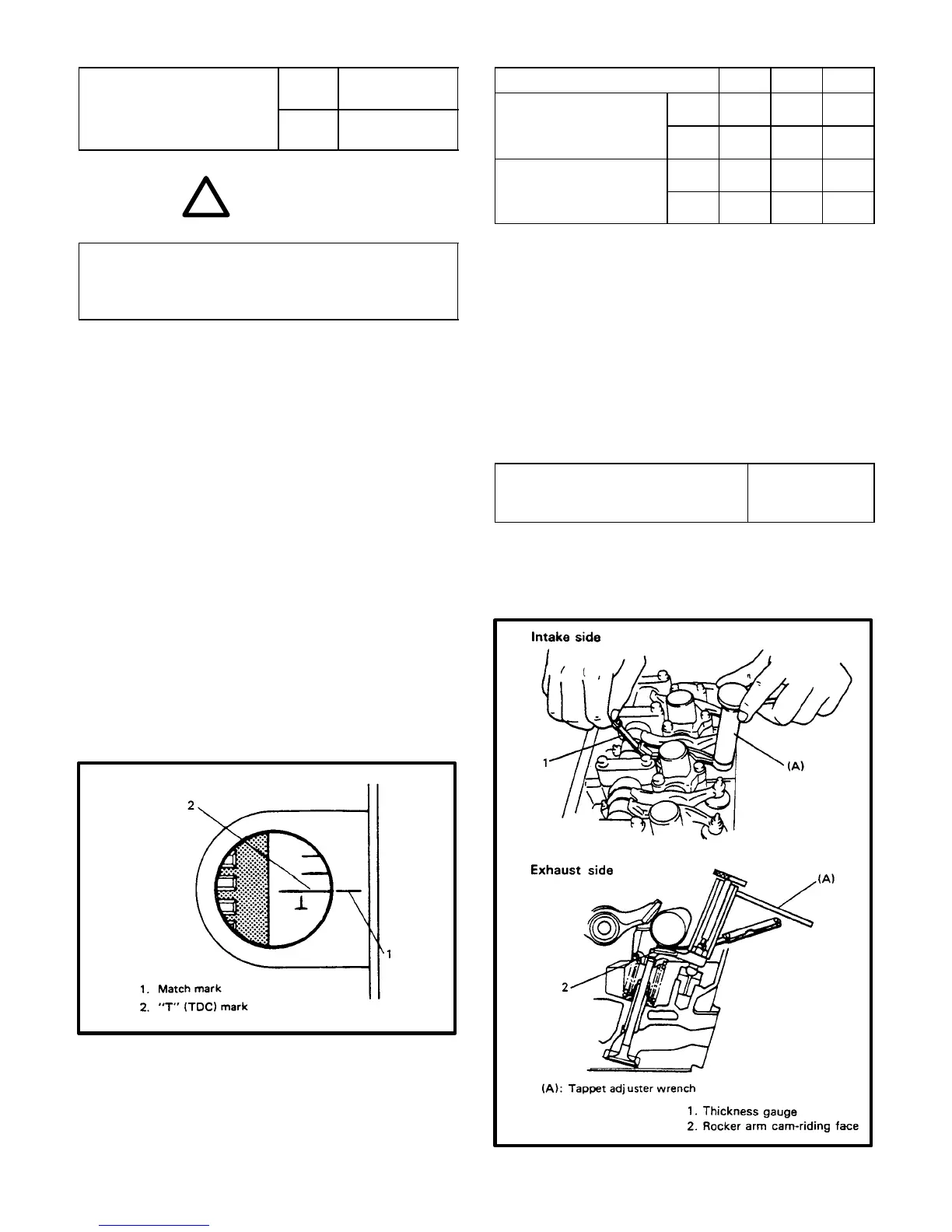
4) Turn crankshaft clockwise (viewing from crankshaft
pulley side) to the extent that line (2) above “T” mark
punched on flywheel is aligned with match mark (1) on
transmission case as shown below, i.e. No. 1 cylinder
piston reaches TDC position.
5) Remove distributor cap and check that rotor is posi-
tioned properly. If rotor is out of place, turn the crankshaft
clockwise once (360°). In this state, check valve clear-
ance according to table below and adjust if necessary
Cylinder Number 1 2 3
No. 1 cylinder
IN X X
TDC of compression
stroke
EX X X
No. 1 cylinder
IN X
TDC of exhaust
stroke
EX X
Valve clearance as marked with “X” in above table can
be measured.
NOTE:
When adjustment becomes necessary in
step 5, loosen adjusting screw lock nut and
then make adjustment by turning adjusting
screw. After adjustment, tighten lock nut to
specified torque while holding adjusting
screw stationary and then make sure again
that clearance is within specification.
Adjusting screw lock nut tight-
ening torque
10–13 N–m
1.0–1.3 kg–m
7.5–9.0 lb–ft